The Concept
I was motivated to develop a vibrating wristband communication device after reading “Enchanted Objects” by MIT Media Lab’s David Rose. In the book, he imagines a future based not around the “cold slab of glass” of our smartphone screen, but instead on “technology that can enhance our five senses and optimize our physical abilities – by accommodating and responding to the way we already operate in the world”.
As I planned my device, I drew up the following wish-list:
- The device should communicate with us in an immediate way that bypasses our usually overworked visual sense.
- The device should have multiple vibrating actuators to be able to deliver a richer message than can be achieved by using “Morse code” like on-off pulses to a single actuator.
- It should use Wi-Fi to connect directly to other devices over the internet. This is in contrast to almost any other similar device either available or being proposed. Of course, the use of Wi-Fi instead of BLE does mean a higher power consumption. But for this proof of concept, I wanted a device that was a “first class citizen”, not requiring tethering to a smartphone or other device. The power issue could be dealt with later, hopefully with sleep modes, advancing technology, etc.
- In keeping with the Internet of Things (IoT) ethos of ubiquity, the device needed to be low cost. This is particularly important for the wristband, because it is explicitly designed as a single function device, not to be all-in-one and consequently complex-to-use as seems to be the current trend.
The ESP8266
The technology required to make this possible (at least from a hobbyist perspective) only became available late last year, in the form of the ESP8266. This remarkable module is tiny, has built in Wi-Fi, a programmable CPU able to control GPIO pins, and costs only about 3 dollars (including free shipping from China!)
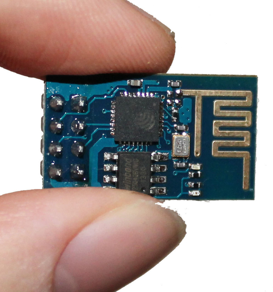
The drawback is that documentation is scarce – although this situation is gradually improving due to a few intrepid developers out there (refer links for details). It also does not run Linux like some other development boards, which means that you have a limited choice of development options (at least currently).
I initially started coding the wristband using Lua, which becomes possible by flashing the ESP8266 with the NodeMcu firmware, using ESPlorer. Although certainly an easy way to get started, in my case the results were flaky. I was constantly getting module resets, and wasn’t sure why. Memory also seemed to run out quite quickly. However, I may not have persevered enough, or the environment may have improved since then. So don’t let me put you off trying – here is a link to download my wristband_lua code.
As a result, with some trepidation, I moved onto using the Unofficial Development Kit by Mikhail Grigorev (forum here), which turned out be an excellent piece of work. It does require that you develop your code in C, which may not be to everyone’s taste. In my case, it is my preferred development language and so, quite a few hours later, I had ported across my wristband code into the “esphttpd” example provided in his SDK.
To my delight, this proved to be stable. Also, the serial bit-banging loops were running 250x times faster as measured on an oscilloscope – not essential for my application, but nonetheless satisfying.
The First Prototype
The main objective was to find out how the multiple vibrating actuators would actually feel when on your arm. Was this a feasible approach to communicate a variety of different messages?
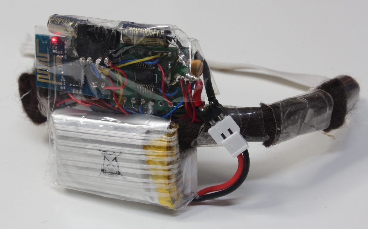
As you may have noticed from the picture at the top of this post, it is not likely to win any product design awards. Having said that, it moved my personal construction techniques into new territory. There is nothing quite like using a microscope to solder together SMD parts across a free blank area of the PCB when afterwards you can hardly see that there is anything there.
I am working on a second prototype that will both look and work better, based on what I have learnt out of this.
Read on to hear the details of how I built this first prototype, and to watch the video at the end.
The Mechanics
The wristband called for sensors to be spaced around the arm. To provide a backbone on which to construct everything, I used a yogurt container, since the plastic already had some of the curvature required to go around your arm.

A piece was cut out which had a thin portion to wrap around the wrist, and a wider platform to hold the battery and electronics.

Six vibrating (pager) motors were acquired off eBay,

and attached to the band using the self-adhesive peel-off sticker, as shown below.
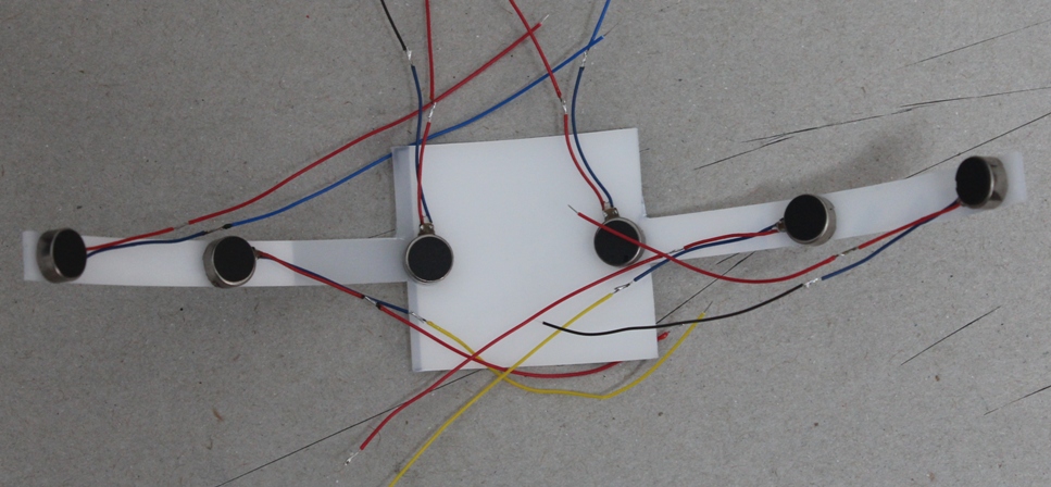
I later modified this design in three ways, because in practice I found that vibrations were being transmitted via the band itself, which meant that each actuator did not feel as localised as I wanted:
- I inverted the actuators as the vibration needed to be directed outwards towards the arm, not back into the band itself. I then covered the new surface of each actuator with a washer.
- I added soft felt material to isolate the band from the actuators.
- I isolated each actuator by cutting the plastic band between each actuator, and then joining the now separate segments together using thread, which greatly reduced the transmission of vibration. Actually the thread I used was dental tape (floss), which worked really well because it is strong yet very flexible, not springy like fishing line. But that choice was only because I had to make a repair in a hotel room while travelling, and that was all I had…

The felt material and actuators were held to the band with Sellotape (sliced in half to be narrower).
Finally the two PCBs and battery were secured with a glue gun, and protected with a laminated film that shrinks with heat (which I had left over from a previous project covering wings of a model plane)

The Electronics
The electronics consists of three main components:
- An ESP8266 ESP-01 module, which handles the Wi-Fi and runs software to serve up a web page and control GPIO ports.
- A board for driving the six vibration motors. Since the ESP-01 has only 2 I/O ports available (unless you want to get even more extreme), a shift register is used to expand these.
- A low drop-out (LDO) regulator which supplies 3.3V to the processor and shift register. The vibration motors are driven directly from a 4.2V single cell LiPo battery, to avoid contaminating the regulated digital supply with motor noise.
Here is a circuit diagram. I did not actually do one originally, but just built as I went along. So I confess this was done after the fact. Also, I have modified it slightly for my next prototype, so, while the principles haven’t changed, there are a few differences from the original model. These are:
- Different voltage regulator. The original was one I had to hand – the XC6222D331MR-G
- ESP8266 ESP-03 version instead of the ESP-01 (see version comparison)
- DPST SMD switch to make reprogramming the device more elegant
(Click to expand in a new window)
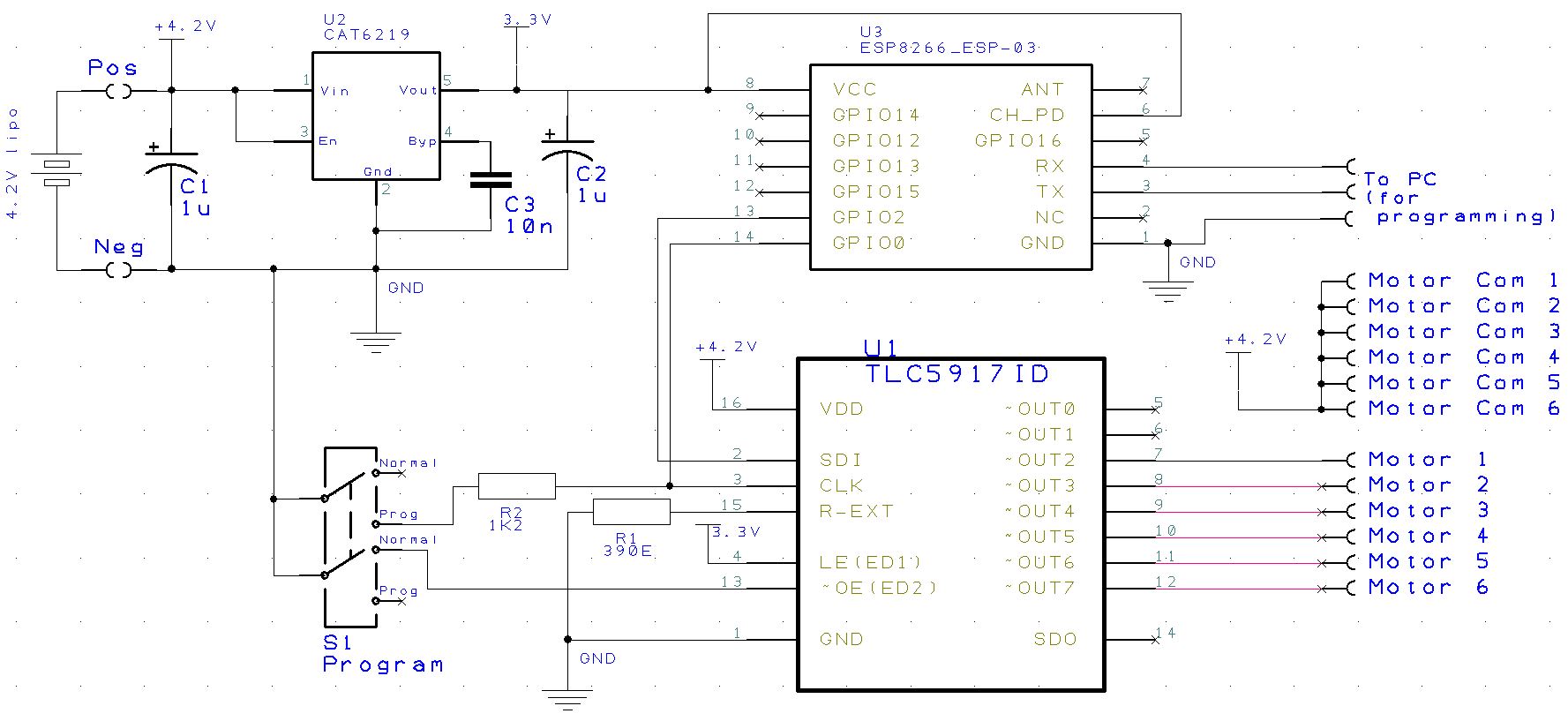
An SMD switch is included to enable programming mode. This holds GPIO0 low on bootup, and simultaneously disables the motors (which otherwise tend to run while the ESP8266 is being programmed).
I came across the TLC5917 device while designing my numitron project, and really like it.

You can set the value of its output sink current for all outputs by means of a single external resistor. In this project I chose R-ext to allow about 50mA to pass through each vibration motor. The other side of the load can be connected to anything up to +20V. In my case I used the unregulated 4.2V from the LiPo battery. Thermal protection ensures that you don’t (easily) destroy the device.
But the real value here is that it requires only 2 lines (clock and data) to give me any number of outputs (since the devices can be chained, taking the SDO of one into the SDI of the next). Strictly speaking, I should also have used the chip’s latch control to prevent transient outputs during the period when new serial information is being shifted in – and I would have if there had been 3 outputs available. In practice, it makes no difference in this project, as the total transient time of about 13μS is several orders of magnitude faster than anything the motors could respond to.
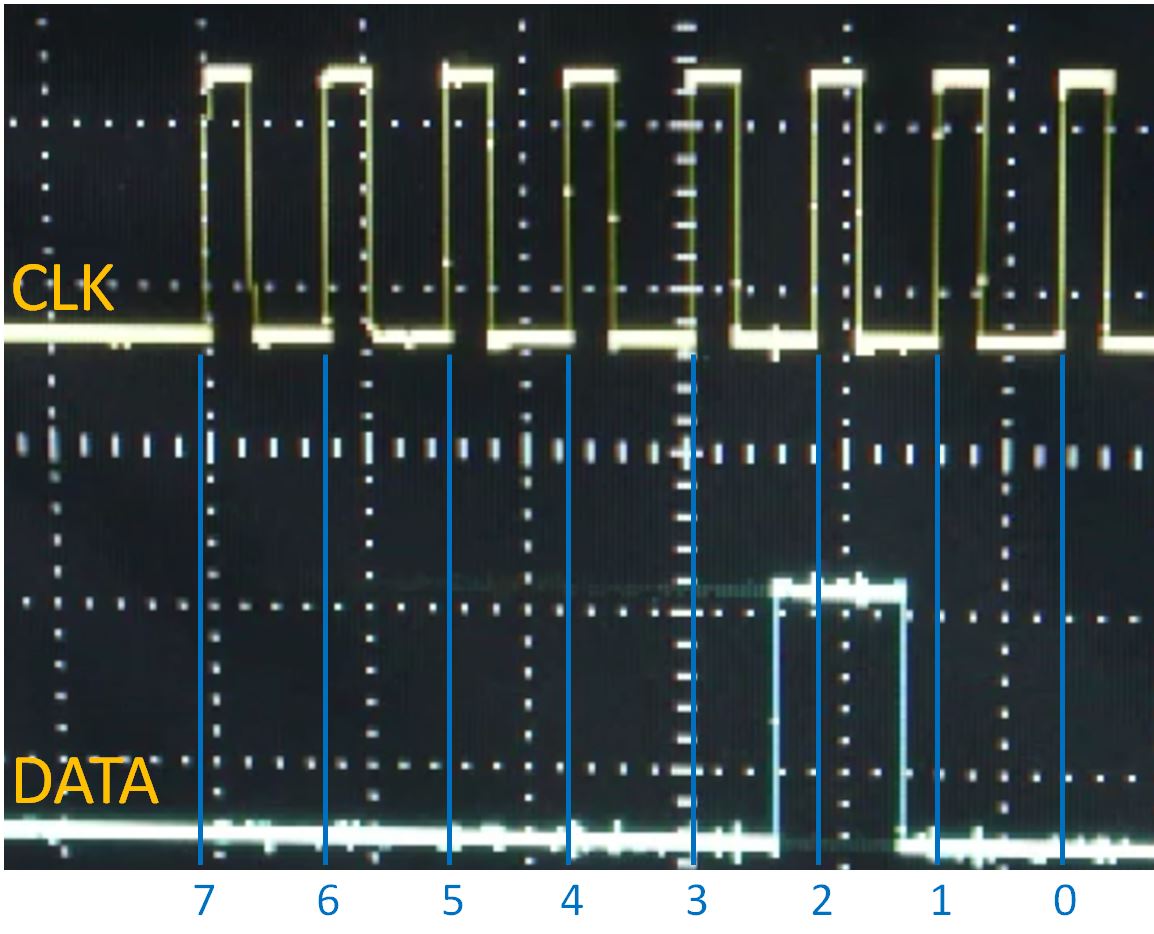
The following picture shows an example in which output 2 is set high (i.e. only motor 1 connected to Out2 will be switched on). The data line is sampled at each rising edge of the clock.
The video clip below shows dynamically what happens when motors 6 through 1 are cycled (a motor is disabled when the next motor starts), with a short pause in between each command. The physical effect of this feels like a rotation around the arm. Although this example shows only one motor on at a time, any number can be enabled simultaneously by setting more bits in the output command byte.
(Maximise the video to view)
The Software
To demonstrate the wristband, I developed a single web page which is served up by the ESP8266. The ESP8266 is able to act as its own hot-spot i.e. generate a Wi-Fi network or alternatively connect to your existing network if you supply the credentials (in include/user_config). Depending which button you select on the webpage, a predefined vibration pattern is triggered. For the final solution, the ESP8266 would listen for a message that is sent from another source via a json command, or possibly through hosting a websocket (if someone can develop/port that code), or maybe even via MQTT.
The webpage simply posts the value of the button that was pressed, and then hides the buttons to prevent multiple submissions until the page has been posted and refreshed. It looks as follows:
<html><head><title>Test</title>
</head>
<body>
<div id="main">
<h1>IoT Wristband Alert</h1>
<h3>Try an alert mode below:</h3><br>
<form method="post" action="led.cgi" onclick="hideBtns(this)">
<input type="submit" name="IAcmd" value="1-Zone">
<input type="submit" name="IAcmd" value="2-Zone">
<input type="submit" name="IAcmd" value="3-Zone">
<input type="submit" name="IAcmd" value="Warning">
<input type="submit" name="IAcmd" value="Emergency">
<input type="submit" name="IAcmd" value="Right">
<input type="submit" name="IAcmd" value="Left">
</form>
</div>
<script>function hideBtns(f) {f.style.display = "none";}</script>'
</body></html>
That works well as a front end screen on which to make your selection, but what about the back end? There are three activities that the code needs to perform:
- Respond to a button press in the webserver
- Initiate a vibration pattern, depending on the button selection
- Actually drive the vibration motors according to a pattern
Fortunately, the Unofficial Development Kit includes the esphttpd example, which handily delivers a web server with an ability to manipulate GPIO ports. I modified the standard code slightly and added in code specifically for the wristband.
Responding to the webserver entails simply responding to the “led.cgi” action in the post. (Yes, I know the name doesn’t make sense, but I kept it from the original esphttpd example).
To do this, a line is inserted in the HttpdBuiltInUrl function within user_main.c
HttpdBuiltInUrl builtInUrls[]={
{"/", cgiRedirect, "/index.tpl"},
{"/led.cgi", cgiLed, NULL},

{"*", cgiEspFsHook, NULL}, //Catch-all cgi function for the filesystem
{NULL, NULL, NULL}
};
This causes the cgiLed function to be called, which is found in cgi.c
int ICACHE_FLASH_ATTR cgiLed(HttpdConnData *connData) {
int len;
char buff[1024];

if (connData->conn==NULL) {
//Connection aborted. Clean up.
return HTTPD_CGI_DONE;
}

len=httpdFindArg(connData->postBuff, "IAcmd", buff, sizeof(buff));
//os_printf("Test:%s\n",buff);
if (len!=0) {
switch (buff[0]) {
case '1':
pulse_double(MOTOR1,MOTOR2);
break;
case '2':
pulse_double(MOTOR3,MOTOR4);
break;
case '3':
pulse_double(MOTOR5,MOTOR6);
break;
case 'W':
pulse_warning(3);
break;
case 'E':
pulse_all(3);
break;
case 'R':
rot_clockwise(3);
break;
case 'L':
rot_anticlockwise(3);
break;

//pulse_single(MOTOR1);
}
}

httpdRedirect(connData, "index.tpl");
return HTTPD_CGI_DONE;
}
Depending which button value has been passed, this calls the corresponding vibration pattern routines, which I added into io.c:
void ICACHE_FLASH_ATTR rot_clockwise (unsigned char loops) {
unsigned char x;
for (x=1; x<=loops; x++) {
putItem(&myQueue, MOTOR1,35);
putItem(&myQueue, 0, 12);
putItem(&myQueue, MOTOR2,35);
putItem(&myQueue, 0, 12);
putItem(&myQueue, MOTOR3,35);
putItem(&myQueue, 0, 12);
putItem(&myQueue, MOTOR4,35);
putItem(&myQueue, 0, 12);
putItem(&myQueue, MOTOR5,35);
putItem(&myQueue, 0, 12);
putItem(&myQueue, MOTOR6,35);
putItem(&myQueue, 0, 12);
}
}

void ICACHE_FLASH_ATTR rot_anticlockwise (unsigned char loops) {
unsigned char x;
for (x=1; x<=loops; x++) {
putItem(&myQueue, MOTOR6,35);
putItem(&myQueue, 0, 12);
putItem(&myQueue, MOTOR5,35);
putItem(&myQueue, 0, 12);
putItem(&myQueue, MOTOR4,35);
putItem(&myQueue, 0, 12);
putItem(&myQueue, MOTOR3,35);
putItem(&myQueue, 0, 12);
putItem(&myQueue, MOTOR2,35);
putItem(&myQueue, 0, 12);
putItem(&myQueue, MOTOR1,35);
putItem(&myQueue, 0, 12);
}
}

void ICACHE_FLASH_ATTR pulse_all (unsigned char loops) {
unsigned char x,y;
for (x=1; x<=loops; x++) {
for (y=1; y<=4; y++) {
putItem(&myQueue, MOTOR1 | MOTOR2 | MOTOR3 | MOTOR4 | MOTOR5 | MOTOR6,20);
putItem(&myQueue, 0, 10);
}

putItem(&myQueue, 0, 20);
}
}

void ICACHE_FLASH_ATTR pulse_warning (unsigned char loops) {
unsigned char x,y;
for (x=1; x<=loops; x++) {
putItem(&myQueue, MOTOR1 | MOTOR3 | MOTOR5 , 20);
putItem(&myQueue, 0, 10);
putItem(&myQueue, MOTOR2 | MOTOR4 | MOTOR6, 20);
putItem(&myQueue, 0, 100);
}
}

void ICACHE_FLASH_ATTR pulse_double (unsigned char pulse1, unsigned char pulse2) {
unsigned char x;
for (x=1; x<=5; x++) {
putItem(&myQueue, pulse1,35);
putItem(&myQueue, 0, 12);
putItem(&myQueue, pulse2,35);
putItem(&myQueue, 0, 12);
}
}

void ICACHE_FLASH_ATTR pulse_single (unsigned char pulse1) {
unsigned char x;
for (x=1; x<=5; x++) {
putItem(&myQueue, pulse1,35);
putItem(&myQueue, 0, 12);
putItem(&myQueue, pulse1,35);
putItem(&myQueue, 0, 35);
}
}
In essence, these routines simply place a series of byte commands (where each bit corresponds to a motor) plus the duration of that command onto a queue which correspond to the vibration pattern chosen by the user. I did this to avoid very long delay loops (in terms of processor cycles), especially after the resetting problems that I had experienced with the lua code. This results in a pattern routine executing very quickly, after which the processor can return to servicing other tasks e.g. Wi-Fi, webserver, etc.
I implemented the queue as a circular buffer (I chose that code source as I figured that anyone going to the effort of drawing such a good diagram would also have good code!). I changed the queue to accept two values: a command and duration.
The circular buffer routines are as follows:
initializeQueue(circularQueue_t *theQueue)
isEmpty(circularQueue_t *theQueue)
putItem(circularQueue_t *theQueue, unsigned char ItemValue, unsigned char ItemDuration)
getItem(circularQueue_t *theQueue, unsigned char *ItemValue, unsigned char *ItemDuration)
I then implemented a ticker routine using a timer interrupt that checks the queue every 5mS, to see if there is any work to do via the getitem routine. The code to set this up is put inside the ioInit procedure:
LOCAL os_timer_t sys_timer;

// Set up a tick timer every 5ms
os_timer_disarm(&sys_timer);
os_timer_setfn(&sys_timer, (os_timer_func_t *)tick_service, (void *)0);
os_timer_arm(&sys_timer, 5, 1);
The 5mS interval gives me enough resolution for different vibration patterns, but also allows for potentially just over a second duration per command with only a single byte. The duration value is therefore in units of 5ms ticks. The ticker variable in the background continuously counts up to 31999 and then back to 0.
LOCAL void ICACHE_FLASH_ATTR tick_service(void *arg) {
int gotitem;
unsigned char nextitem, nextduration;

ticker++;

if (ticker >= 32000) {
ticker -= 32000;
}

if (ticker == waitingForTicker) {
waitingForTicker = -1;
}

if (waitingForTicker < 0) {
gotitem = getItem(&myQueue, &nextitem, &nextduration);
if (gotitem) {
waitingForTicker = ticker + nextduration;
if (waitingForTicker >= 32000) {
waitingForTicker -= 32000;
}
shiftOut(nextitem);
}
}
}
When the ticker routine determines that there is something to do, the shiftout procedure accomplishes it by toggling the clock and data lines of the hardware shift register as described earlier:
//Send command byte via serial to shift register
void ICACHE_FLASH_ATTR shiftOut(unsigned char command) {
unsigned char x, databit;
//Initialise latch low to start sending data
//This can only be enabled for ESP8266 modules that break out more than 2 GPIO pins
//GPIO_OUTPUT_SET(LATCHPIN,0);

//Init clock to low
GPIO_OUTPUT_SET(CLOCKPIN,0);

for (x=1; x<=8; x++) {
databit = command & 1;
//Setup the data
if (databit == 0) GPIO_OUTPUT_SET(DATAPIN,0); else GPIO_OUTPUT_SET(DATAPIN,1);

//Clock out the data
GPIO_OUTPUT_SET(CLOCKPIN,1);
GPIO_OUTPUT_SET(CLOCKPIN,0);

command >>= 1;
}

//Latch the new data to shift register output
//GPIO_OUTPUT_SET(LATCHPIN,1);

GPIO_OUTPUT_SET(CLOCKPIN,0);
}
Note the commented out code for properly implementing the latch of the shift register when I use the ESP-03 version of the ESP8266, which has additional GPIOs available.
The final video
The result in use is quite intuitive. For example, a rotating sensation around your wrist in one direction can mean “right”, and in the other direction “left”.
Well, if you have made it this far, you deserve a video. Enjoy, and follow my blog for updates!
[wpvideo TIySIoiN]
Hi, met at AMCouncil. Very impressed with your work. One day my boys might get this. Phil from IBM Maximo
Thanks for the kind words Phil. Keep encouraging your boys! By the way, I have just posted details of the train you saw earlier this week here
Just wondering if you ever got around to developing a second prototype of this tech? I am very interested in this!
Unfortunately I got busy on other things. And, to be honest, there was not too much interest… Apple introduced their haptic feedback watch not long after this post. Although I was aiming to do something fundamentally different to them, i.e. to convey complex information via a different sensory medium (as opposed to just generating different flavours of alerts), most people don’t see a need for this, at least currently.
However, I am keen to revisit in the future! In particular I wanted to try out using “phantom sensation, where two vibrotactile actuators placed closely together on the skin create the illusion of a single vibration between the two
actuators”: https://www.cs.umd.edu/~jonf/publications/Hong_EvaluatingAngularAccuracyOfWristBasedHapticDirectionalGuidanceForHandMovement_GI2016.pdf
Also have a look at this startup: https://wearmoment.com/