A frequently touted promise of IoT is to make your life easier by making everyday objects smarter. This has led to a slew of connected devices targeted at the consumer.
I don’t know about you, but many of these products seem to be targeting a need that I didn’t realise I had, rather than being genuinely useful.
Instead of developing yet another solution in search of a problem, I decided to address a very real need in our household. Due to busy schedules, I often find myself in the supermarket on the way home from work, trying to remember what food needs buying. It seems that I am not the only one experiencing this situation. Compounding this problem is that my teenage sons can consume a LOT, but what they are consuming at any point in time is erratic and difficult to predict.
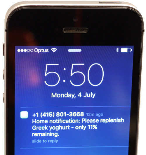
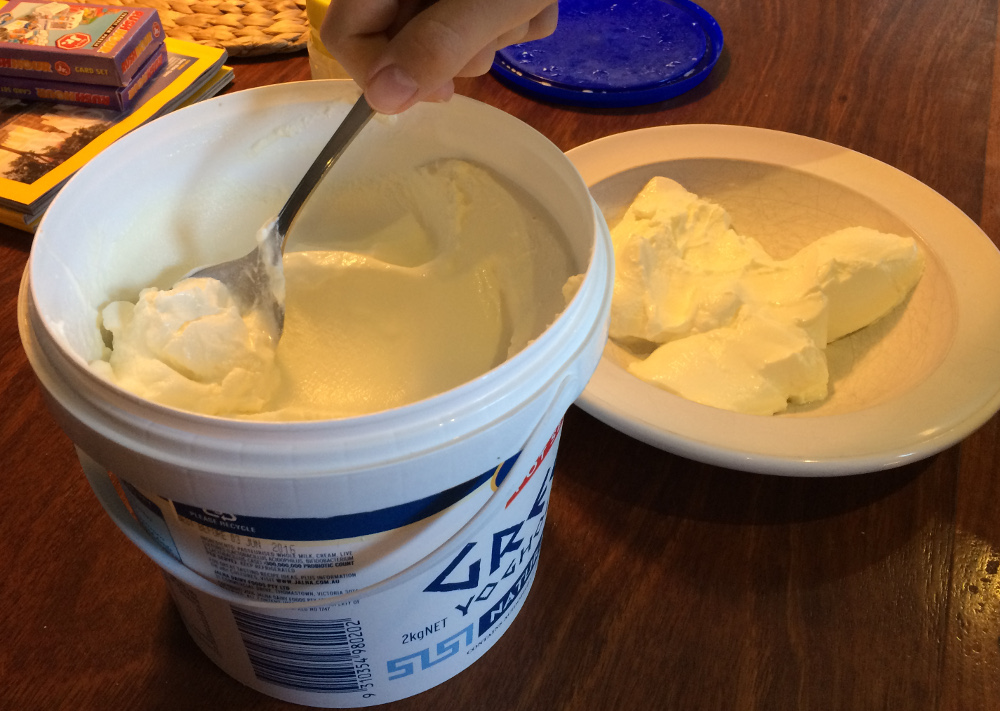 As an example, we recently went through a (relatively healthy) phase of consuming Greek yoghurt. To keep up with demand, we standardised on buying a 2kg (4.4lbs) tub – but only one tub at a time because of the space it occupies in the fridge. Unless I have recently eaten some, it becomes guesswork as to whether or not to replenish. And, in case you’re wondering, forget about getting my sons to proactively flag that anything is running out.
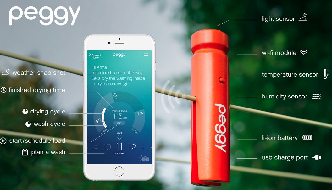
 Time to hack together something to automatically give me that information, whenever and wherever I needed it. Yes, I could wait for a product (most likely at substantial cost) to be available like the smart mat demonstrated at CES 2016… but what would be the fun in that?
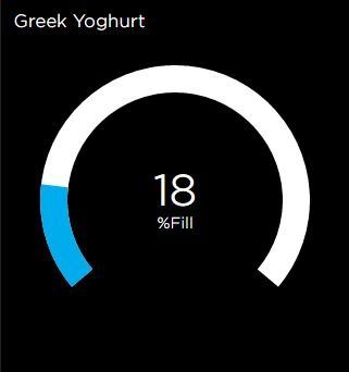
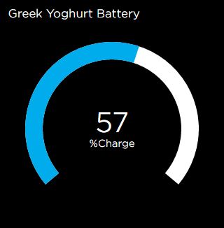
 Fortunately, with a NodeMCU, some clever (at least I think so) Arduino code, the Adafruit IO cloud platform and a weight sensor, we have all the ingredients to build a device that will let us check the current yoghurt level on a smartphone at any time, and also send a text alert if supplies hit a critical level, all at a very low cost (excluding your time of course).
You can experience a live version of my yoghurt monitor here.
As you read on, keep in mind that this approach could be generalised to monitor any container. Also, the strategy would be to have multiple of these or similar devices. With many devices, it would be annoying to receive alerts every time something needs replenishing; instead, I imagine that they would update an automated shopping list, ready for when you are in the store.

Sensing Container Weight
The simplest and most generic way to monitor how much is left in a container is to use weight. 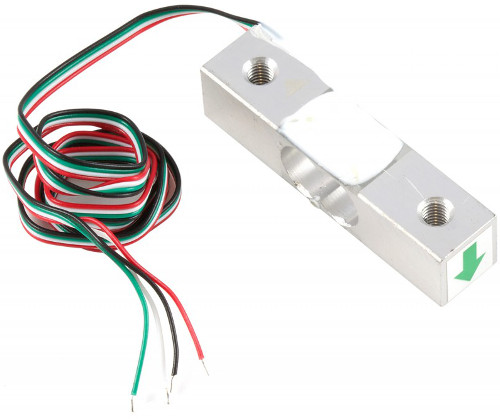 For low cost and good accuracy, load cells offer an attractive option. Having not used these before, I was pleasantly surprised by how easy to use and accurate they have proven to be.
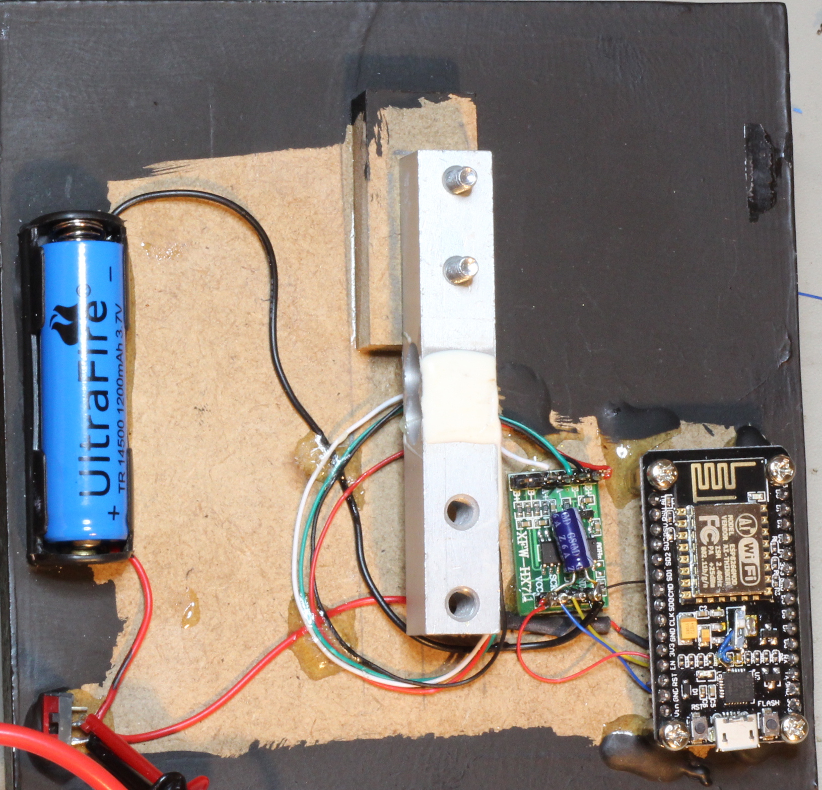
A quick search reveals no shortage of options. For my purposes, I chose a 5kg sensor. The output of the sensor will require considerable amplification; fortunately, an HX711 module takes care of this and provides serial data able to be interfaced directly to two GPIO pins on the NodeMCU.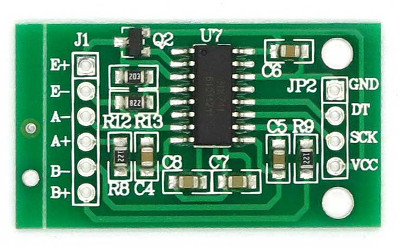
The final piece of the puzzle is to include an HX711 library within the Arduino code, which takes care of interpreting the serial stream.
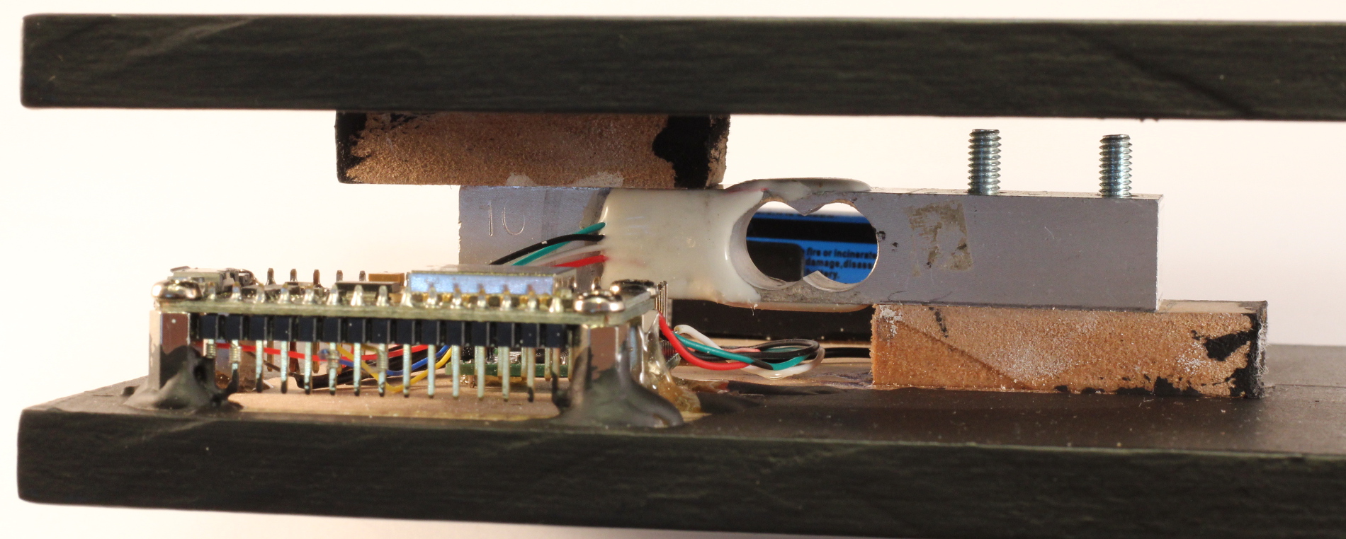
In terms of the physical build, I simply used two pieces of 6mm (1/4 inch) MDF, with the load sensor attached between them.

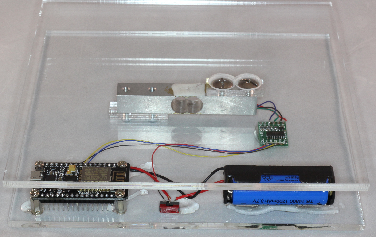 [Update 6 Aug 2016]: I have now made one out of acrylic, having done a layout in inkscape, which was then laser cut at Ponoko. I chose a transparent colour because this is for an IoT demo, but one of the translucent colours would probably be more attractive.

Battery Power
The key to making this project viable is battery power, mandated because running power wires into our fridge would have a very low WAF. Even for a more general case, most pantries are unlikely to have a power outlet handy. In any event, powering multiple containers would get messy very quickly.
In my last post, I covered one approach to reducing power consumption, whereby I deploy a user-friendly NodeMCU running off a single AA sized Li-Ion cell, with an expected battery life in the order of several months. Alternatively, you could deploy a bare ESP8266 – say the ESP-12E, provided it exposes GPIO16 and RST for you to link – plus add the required support components yourself.
The real trick to achieving low power consumption, once you have suitable hardware, lies in software, which I will discuss later in this post.
Circuit
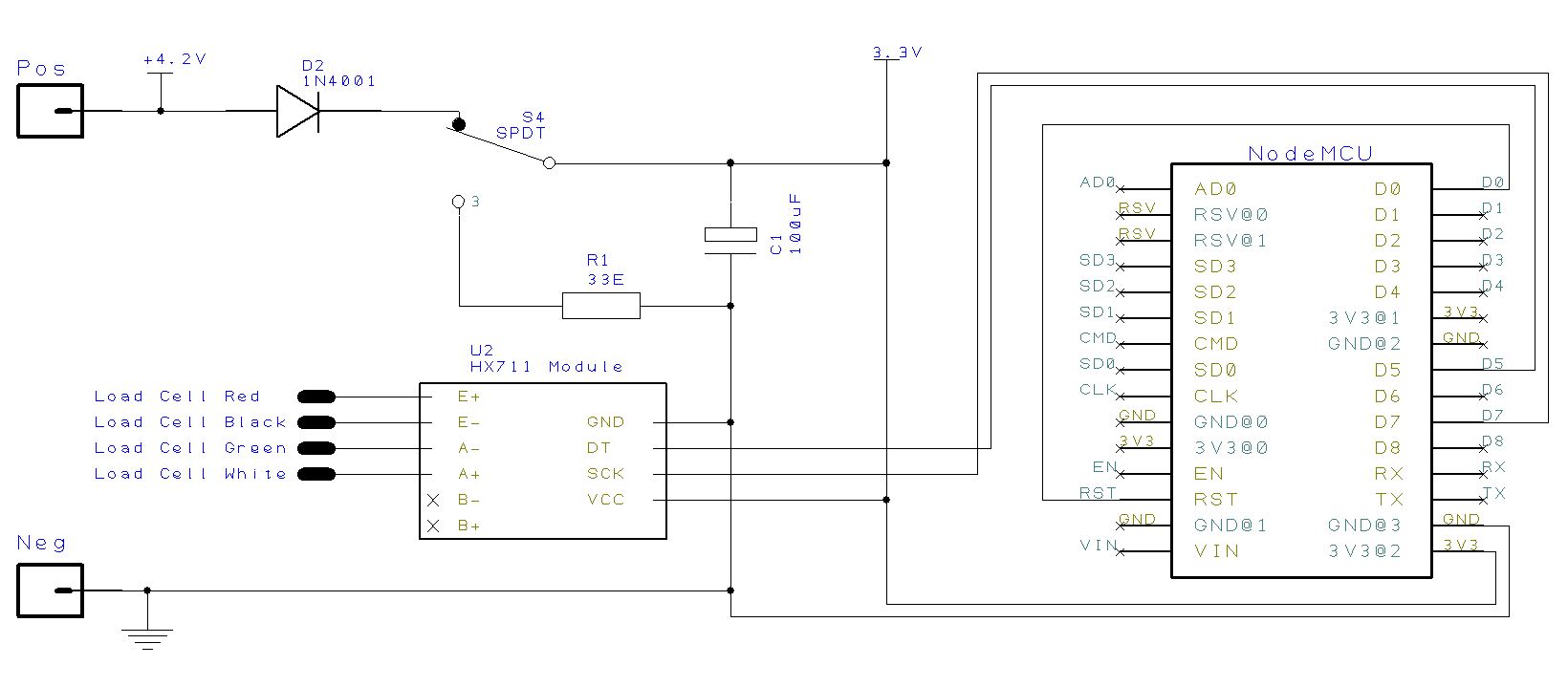
 The circuit consists of a NodeMCU with the RST and GPIO16 pins tied together to allow it to be awoken from deep sleep by the real time clock (RTC).
The HX711 module already mentioned is connected via two pins used for the serial clock and serial data.
The USB serial connections are not shown on the schematic, since the USB port is built into the NodeMCU board.
You may be wondering what the two pole switch is for. Its purpose is to discharge C1 when switching off the unit, otherwise the charge on C1 will maintain the RTC memory for some time, preventing a cold restart in which the NodeMCU checks for any new over-the-air (OTA) updates and recalibrates the scale to zero.
The schematic is shown below, captured in Designspark and using a converted Eagle footprint for NodeMCU.
Software
The Arduino for the ESP8266 development environment was used. The main reason that I started using the Arduino IDE was that makes it much easier to share the resulting code with others compared to using the native SDK. Also, I like the Over-the-Air (OTA) capability that can be enabled merely by adding a few statements into your code. It is faster and more convenient – especially if you have disabled your UART to save power – to update software over Wi-Fi instead of over the USB port. Finally, it doesn’t hurt that there is a huge Arduino codebase out there, containing many libraries that can be reused, some with little or no modification.
To reduce power usage, the container weight is sampled every 15 minutes. Only if there is a change to report (including say a low battery warning) will the Wi-Fi be enabled, the update sent, and the device returned to deep sleep.
The code is slightly unusual in that everything happens in the setup() function, in contrast to a typical Arduino sketch in which most of the functionality is in the loop() function.
In my case, the loop() function is empty because the mode of operation is to wake-up from deep sleep, run once through the required functions, and then return to sleep. There is no continual looping.
This raises a potential problem: for OTA updates to work, an OTA function has to be called at least every 2 seconds – typically done in the main loop. Clearly, OTA will not work with the ESP8266 sleeping for most of the time. To get around this, after a cold restart, the code waits for 10 seconds to see if the “flash” button is pressed. If pressed, the ESP8266 will wait for an OTA update.
When waking up from sleep, the MCU first checks to see if this is the first run, in which case some initialisation is required including calibrating the scale. As a result, it is important to ensure that there is no container on the sensor for the first 5 seconds after power is switched on.
 On subsequent awakenings from deep sleep, both the weight and battery voltage are measured. After that, the following checks are performed:
- If the weight has changed by more than 10g, an update of weight and battery voltage will be sent to the Adafruit IO cloud.
- If the weight is less than a defined threshold, a “buy more” alert will be sent via IFTTT to your cellphone, but only once.
- If the battery is less than a defined threshold, a “replace battery” alert will be sent via IFTTT to your cellphone, but only once.
 To allow this to work, it is necessary to persist across sleep cycles the last values of weight, scale calibration and warning flags (to prevent multiple warnings being sent to a phone once a threshold has been reached) .
Instead of saving this data to flash, which has limited write cycles, I used spare memory within the RTC, which luckily persists during deep sleep. A suggestion for the code to use can be found here. Note that the RTC memory will be reset when switching off – provided any residual capacitor charge is also drained, as described above. This will trigger a full initialisation on start up.
I have directed the ADC of the ESP8266 to measure its supply (battery) voltage by declaring ADC_MODE(ADC_VCC).
My full code can be found on github.
Adafruit IO
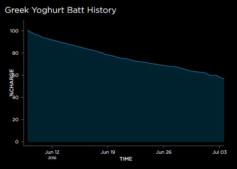
I thought that I would try out Adafruit’s cloud service offering, Adafruit IO, which is still in beta and free. Although quite limited in features (please Adafruit could you allow more than 1 month of low volume data to be stored?), it has a great looking UI and is very easy to use, with heaps of good tutorials.
What really got me interested is that Adafruit IO works with MQTT, this being the protocol I almost always use for my IoT devices. Note that, although Adafruit has their own MQTT library, I am more familiar with using the standard Arduino PubSubClient library, as for example in my smart shelf. This required a bit of fiddling, but you can either refer to my code, or follow the Adafruit recommended approach, which replaces pubsubclient.
I am not going to repeat their excellent documentation here, which then takes you through creating a data feed and building your dashboard.
You could also consider connecting your Adafruit IO data feed to IFTTT, although I ended up interacting directly with IFTTT via their maker channel.
A note when building the dashboard: I found that the only way to ensure that dashboard blocks (i.e. graphs) displayed in the correct order on a mobile device was to add them to the dashboard in reverse order.
IFTTT Maker channel
IFTT provides a cloud offering that is handy for linking your devices together. Specifically, the IFTT Maker Channel allows you to include your own IoT gadgets as described in this post. One of the actions that IFTTT offers is to send an SMS message to a cellphone, as this person has done. This is exactly what I needed for the alerts in my application.
 A note to those living outside North America: IFTTT imposes a limit of 10 free texts per month. This is quite reasonable, since presumably they incur costs. Although a single container is not likely to generate this many alerts in one month, when testing your application you can rapidly exhaust this allowance – as I unwittingly did. Furthermore, if monitoring multiple containers, the limit could become problematic.
For this reason, I intend to make a change from SMS to using IFTTT’s own Notifications, even although it requires the installation of an IFTTT app on your mobile device.
For all its amazing connectivity, I was surprised and disappointed to find that IFTTT does not include basic logic functionality… like “AND” for example. I wanted to create a recipe that only sent an alert when my container level was below a threshold AND I was geographically close to the supermarket. You can do either of these tasks in IFTTT separately (see here for geofencing), but not the combination of both.
Configuring the Software
You will first need to update the code with your own configuration by editing Config.h as follows:
ssid: Your Wifi station name
password: Your Wifi Password
mqtt_server: leave as “io.adafruit.com”
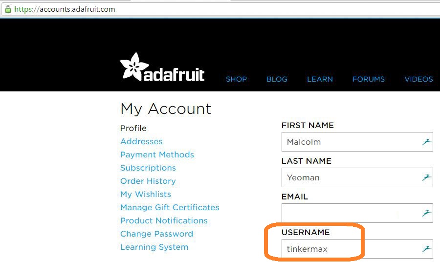
mqttuser: Your Adafruit Username
mqttpwd: Your secret AIO key (which will be accessible from https://io.adafruit.com/<Your Adafruit Username>

iftttMakerUrl : https://maker.ifttt.com/trigger/<Name of your Maker Event>/with/key/<Your Maker Channel Key>, which can be found at:

Using the Software
- Install the HX711 library.
- Flash the code (with your configuration) to a NodeMCU via its USB port. You can then modify the NodeMCU to reduce power consumption, and thereafter use OTA updates. To apply an OTA update requires a cold restart (i.e. a startup where the RTC memory has been cleared). After switching on, wait a couple of seconds, then hold the flash button for at least a second. You can then start the Arduino IDE and flash via the network port.
- The software recalibrates to zero immediately after a cold restart. So ensure that there is no container on the load cell for the first 5 seconds after switching on.
Further Power Saving Ideas
I have been running off the same 14500 battery for almost 2 months and at 31% charge, it should last for about 3 months. This if fine for my purposes, but there are certainly further enhancements that could be made to extend battery life even further. Here are some ideas:
- Reduce the rate of sampling. Currently, I check the weight
every 15 minutesevery hour, which is overkill. For the purposes of shopping, checking only once or twice per day would normally be sufficient for most types of product. - Use a larger battery, since space is not at a premium. As an example, for the next build I will trade up from the 14500 to a slightly physically larger 18650.
- Remove the onboard led, which flashes on every reset/wake cycle.
- Optimise the code by removing unnecessary print statements, delays etc. [I have now added a DEBUG comment line that allows removal of all serial activity].
Very nice work! I’ve been looking for projects with the ESP8266 to keep me busy.
Thanks, and be sure to share your creations with us!
Great project! We built something similar to check out the status of our milk cartoon, and used Adafruit IO for data logging.
I read your note on displaying the Adafruit IO dashboards on a mobile device, and we found that a bit clumsy as well. So we built a free app for iOS and tvOS called DataFeeds that displays data from Adafruit IO. Check it out here: http://datafeeds.monohelixlabs.com
Great article! I also love your power saving article even though I still have to find the courage to start cutting traces on the board. How much current does this unit draw in deep sleep ? I tested deep sleep power consumption on a v0.9 and v1 board (no modifications) and was surprised the v1 board consumed as much as 11 mA where the v0.9 was flipping between 0000 and 0.001 (my multimeter is not very precise)
Anyway, thanks for sharing!
I measured the NodeMCU in deep sleep at 20uA. The entire circuit (including HX711) seems to take closer to 50uA. Possibly that could be improved, but I havent looked at it since as the IoT Container lasts over 7 months on a single charge of a 14500 cell (AA size), which is “good enough”.
Hello! Congratulations on the project, I’m having difficulties with a NodeMcu V3, the error is:
ets Jan 8 2013, rst cause: 4, boot mode: (1,6)
wdt reset
Have you ever been through this?
Thank you
I had not made the jump to the 16 pin RST. Sorry
Camalau: glad you got it to work in the end!
I need help. I don’t getting anything on serial monitor except Booting.
Congratulations on this project. i am finding trouble with the code. There is no response on the serial monitor. I have not connected the external power or the capacitor.
Should that cause this problem
Thank you for your post. I learned quite a lot from it and will reuse some of your code with my projects. You also provide invaluable information about reducing NodeMCU power consumption.
For notifications I found Telegram bot using Universal-Arduino-Telegram-Bot library the most convenient way. If you are already using Telegram messenger, you don’t need to install any additional software and I can read messages on multiple devices.
Good afternoon from Spain.
Thank you very much for your project.
Long ago I mounted a similar one with a modified bathroom scale, but the weight was not very unstable
because of the temperature, and I had problems with wifi coverage inside the refrigerator.
I am assembling your project but when compiling it gives me this error
“exit status 1
‘class PubSubClient’ has no member named ‘setServer’
thanks for your help