I am intrigued by the notion put forward by David Rose (seen here presenting at TEDx) of “putting magic in the mundane – that is, having ordinary items that can do extraordinary things”.
I find compelling the notion that for everyday activities there will be a swing in popularity away from having to interact with complex abstract worlds behind glass screens toward a more “authentic” physical experience, for which we humans are so well adapted. But this shift will only be made possible by means of even more advanced technology – able to hide its own complexity.
This month the popular “Thomas the Tank Engine” toy celebrates its 70 anniversary. As a fun project, what could be more appropriate than to bring this traditional toy into the age of IoT, while preserving its physical appearance and simple charm?
For a short overview / teaser, watch the following video (be sure to select HD):
Inevitably there will be those who see this and ask “why?”
The short answer is that, as Hackaday believes, “why” is the wrong question.
A longer answer is that the train is simply BETTER when you can control its speed (remotely over wi-fi), more consistent to operate, especially at low speeds because of an auto “throttle-boost” that kicks in when the accelerometer senses that the train is going uphill, and more user-friendly with remote monitoring of the battery state.
And if you need still more justification, the Train appeared this week at a trade exhibition as a source of IoT data to demonstrate business software (go to YouTube here if you are interested, where one of my colleagues explains).
The main challenge was to be able to fit the required electronics into an existing form factor. As it transpired, the toy train was a lot more compact than I had anticipated. I had to undertake some delicate “surgery” to free up space underneath the train and behind the front face, but this was done in a way that a casual observer would not notice.
ELECTRONICS:
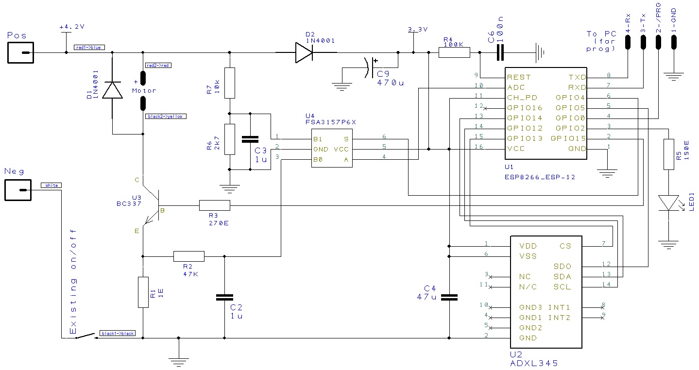
The key component – and what makes this build even possible – is the ESP8266, which functions as both the MCU and provider of Wi-Fi connectivity. It does all the heavy lifting, together with a handful of other components, as shown in the schematic (click to enlarge):
Beyond the specific features that I will discuss separately below, it is worth mentioning the power supply.
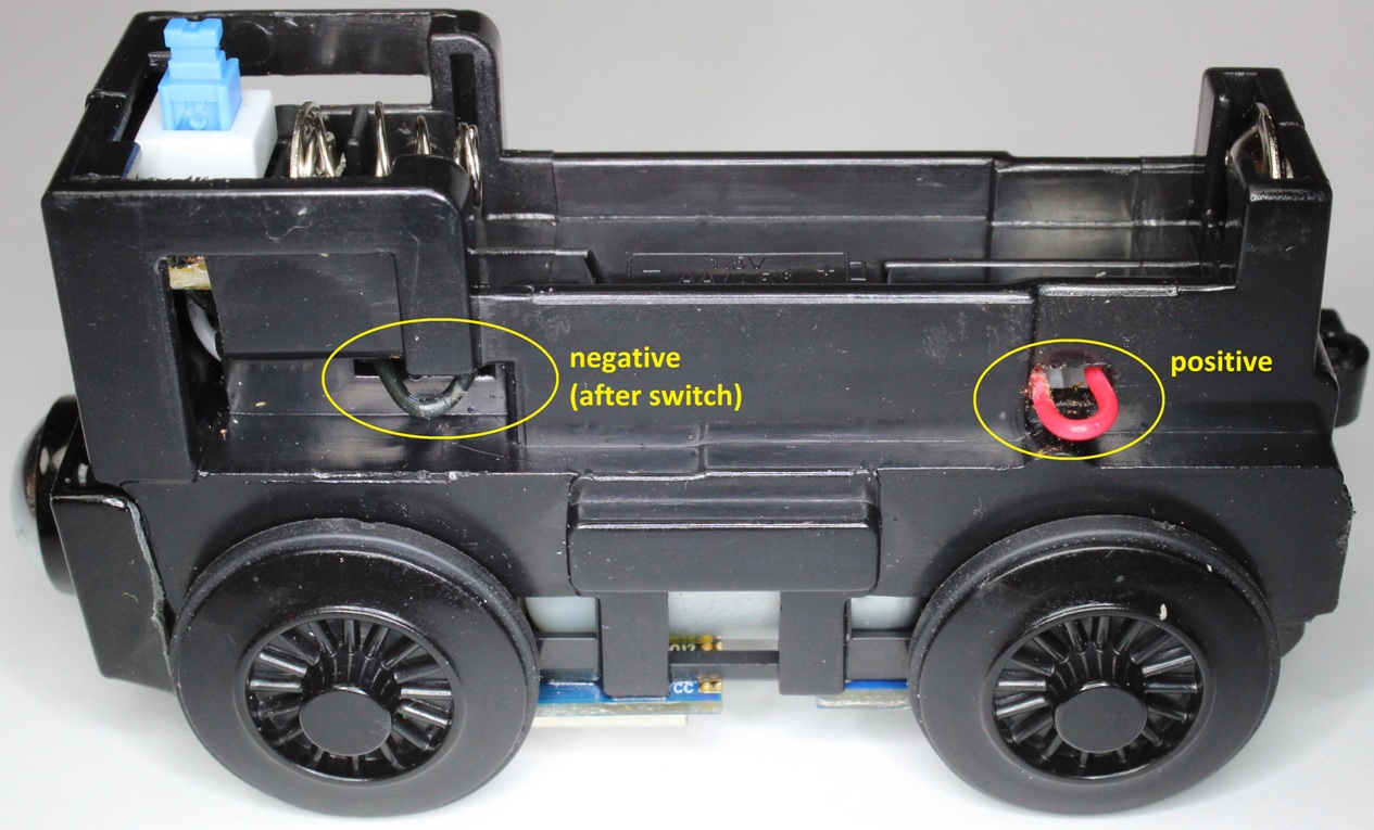
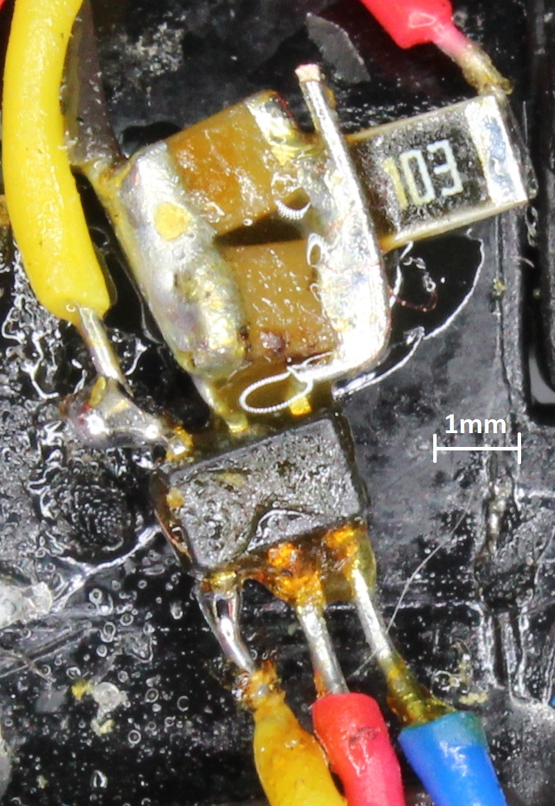
The original toy train was designed around a single 1.5V AA battery, which I could tap into by breaking wires as shown in the photo (without completely disassembling the train and losing cogs, etc). Originally I had planned to use a dc-dc step-up booster, so tried a couple of modules. Quite apart from the size issue (which meant that I was not sure where to hide it on the train), I found in the bread-boarding stage that the ESP8266 would not start up.  I suspect that the modules were not able to deliver the peak spikes required by the ESP8266.
So, after some lateral thinking, I discovered that there exist li-ion batteries of AA size but with a voltage of 3.7V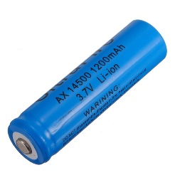
 ! Fantastic what you can discover on Google…
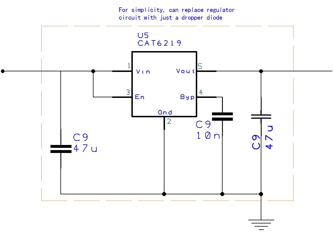
The next issue was how to provide 3.3V to the ESP8266 given that the li-ion has a fully charged voltage of 4.2V – which is too high. Originally I designed the circuit using the CAT6219 as shown in the schematic on the right and below on a breadboard compatible breakout PCB. I still think this would have been the best approach.
 However, due to delays in obtaining a suitable breakout board, I settled on using a simple rectifier diode to drop the battery voltage by 0.6V, which has actually worked out surprisingly well. Since the ESP8266 operates in the range 2.8V – 3.6V, this corresponds nicely to a planned battery operating range of 3.5V – 4.2V.
ACCELEROMETER:
 An accelerometer is used on the train to perform 3 functions (although this could conceivably be extended):
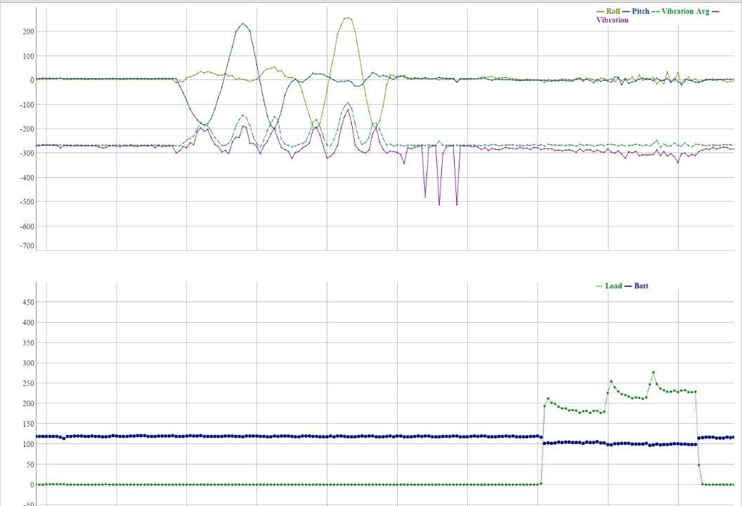
- Pitch angle (e.g. sense when the train is going up or down a hill)
- Roll angle (i.e. side-to-side movement, used mainly to detect anomalies, for example if the train derails and falls on its side)
- Vibration (i.e. up and down movement, used for monitoring track quality)
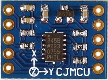
I already had an ADXL345 accelerometer module, so used that. I set the chip sample rate to 400Hz to ensure that when I sampled the ADC at 166.6Hz I would always get a new update. This was important because of the multiplexing I used (see the next section) which meant that consecutive samples would be related to different analog channels.
The device uses serial communication (i2C or SPI). Because of the SPI clock polarity required, I ended up writing my own spi “lite” library. I wrote about that and the accelerometer in a previous post.
ANALOG MEASUREMENTS
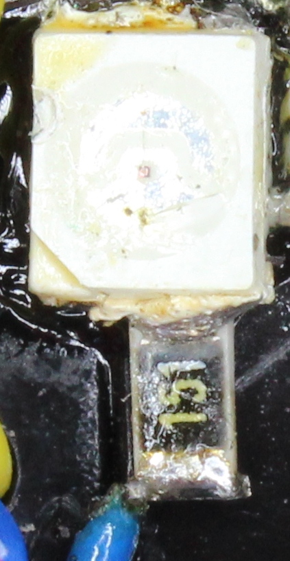
 I placed a 1Ω resistor in series with the motor to be able to measure current (i.e. motor load), and smoothed the result with a low pass filter because of the PWM driven on-off activity.
I also measure the voltage of the li-ion battery, before the dropper diode. This is important to allow proactively swapping the battery before train performance suffers or the battery is damaged through excessive discharge. In a larger/business context (mentioned near the start of this post), this functionality can be combined with predictive software to illustrate the concept of predictive maintenance.
 Since the ESP8266 has only one ADC input, you may wonder how this was done. Rather than introducing another external ADC (with its associated complexity and space requirements), I used an analog switch toggled by a single ESP8266 GPIO pin to multiplex both analog sources onto the single ESP8266 ADC input, as described in a previous post.
SPEED CONTROL AND FACE LIGHT
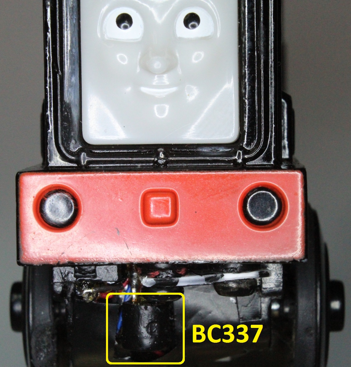 Probably the least complex but immediately useful enhancement to the train is speed control. This is accomplished quite simply using the PWM functionality built into the ESP8266 – i.e. I send an MQTT message containing a value that represents the desired pwm duty cycle. An external transistor is used to drive the motor.
I wanted to use a 2SD1012 so that I could fit it behind the face but could not get delivery in time, so I used a BC337. Although it has worked very well the larger thickness meant that it has to be left exposed at the front. However, in practice, it just looks like part of the train.
A flywheel diode is used to prevent the high voltage spikes created by the motor inductance and PWM switching from destroying the electronics. This is critical to the circuit. I know, because I originally tried a 1N4148 small signal diode (because of its much smaller dimensions) and instantly blew both the diode and the transistor…
 A second PWM output is used to fade the face light in and out. Here I limited the current to less than the recommended 12mA that the ESP8266 is able to supply, so no external driver transistor was needed. With hindsight, I would have added a transistor as the light could ideally be brighter.
To decide on the PWM frequency, I picked one that would be low enough not to be audibly annoying, but high enough to be able to filter out for measurements. I chose 293Hz to avoid any sampling correlations.
The ESP8266 code is simple enough.
You need to first specify the pins in pwm.h that will be used for PWM. In my project these were GPIO 2 and 15.
#define PWM_0_OUT_IO_MUX PERIPHS_IO_MUX_MTDO_U #define PWM_0_OUT_IO_NUM 15 #define PWM_0_OUT_IO_FUNC FUNC_GPIO15 #define PWM_1_OUT_IO_MUX PERIPHS_IO_MUX_GPIO2_U #define PWM_1_OUT_IO_NUM 2 #define PWM_1_OUT_IO_FUNC FUNC_GPIO2You then can use PWM as follows:
//initialise LOCAL uint8_t pwm_duty=0; pwm_duty = 0; pwm_init( 293, &pwm_duty); //set frequency and intial PWM duty cycle //thereafter, when you want to change the PWM duty cycle pwm_duty = [some value]; pwm_set_duty(pwm_duty, 0); pwm_start();WEB PAGE MONITOR
Real time sensor updates are streamed 5 times per second via the MQTT protocol to a Raspberry Pi MQTT broker under the train table. I developed a webpage containing javascript to receive the MQTT messages from the Raspberry Pi (over websockets) to display the sensor data.
Rather than repeating the information, please see my previous post.
POSSIBLE EXTENSIONS
I would have liked to be able to measure train speed accurately for many reasons, for example to implement “cruise-control” to ensure constant speed even up and down inclines. Without this, the train speed cannot be set too low or else it stalls on hills. As a workaround, I used the pitch axis of the accelerometer to give a crude speed-boost on hills. Although this works well in practice it does not take into account, for example, a drop-off in speed as the battery wears down.
Possibly someone else has some ideas?
Good afternoon, great work I must say!
I am trying to develop a project and I need something similar to do it, could you give me some hints? Maybe just a talk to clear some doubts of concept that I have. I’ve been struggling through the web but I couldn’t figure it out.
Sure, what do you need clarified? Put it down in writing and I’ll see if I can help.
Wow! Even though I’ve worked with MQTT and ESP8266 before, and I’ve been obsessed with finding hacks for wooden trains since my son was born a year ago, I must admit I never imagined there would be a way to combine them!
This project is certainly far more complex than other comparable projects I’m aware of. There’s a well-documented effort to build an RC wooden-type locomotive at- http://www.gothammachine.com/2014/05/08/brio-meets-arduino/ and there’s an interesting Raspberry Pi hack posted in a recent issue of the “MagPi” magazine- https://www.raspberrypi.org/magpi/the-story-train/.
I’m especially interested in finding ways to make the wooden trains operate more like the much more expensive electric model trains, since there a few companies like Whittle Shortline and Munipals which make more realistic rolling stock. I also tend to see the wooden-style tracks as more in the open source/maker spirit since the tracks all follow a simple, standardized form.
Some things I’ve considered but not yet attempted-
1-Some kind of indivually addressable trigerring mechanism which could be embedded in the tracks. The RPi article poses a relatively simple method using reed switches to detect when the magnetic couplers pass by, but such a method would be limited in how many actions could be configured. RFID/NFC would be another approach, but it would be much more challenging to embed the sensor in a wooden track (at least without a bunch of exposed wiring which could pose a safety risk for small children)…
2- Hacking a cheap, generic RC controlled engine like this one- http://www.target.com/p/all-aboard-r-c-locomotive/-/A-16740600 by replacing the cover with a generic-looking baggage car/boxcar and adding a magnetic coupler to the front. This would allow existing unpowered “engines” like THomas etc… to be placed on the front as dummies. Also, I’ve found that, much like with real trains, the most efficient motive power is achieved by placing a unit one or two cars BEHIND the front of the train with another unit set the same distance from the rear in long consists. I’ve managed to pull extremely long trains up steep rising tracks with only two small battery engine using this method.
All in all, I would love to see some kind of a discussion group formed around various hacks for wooden (e.g Brio, TTTE etc…) trains as such information is hard to come by.