Welcome to this first post on my blog. Over the years I have enjoyed following and using the work of many others across the Internet, so have decided to contribute my efforts to the community as well.
I have always had a passionate interest in electronics (refer to About), but these days it is very much a hobby. So, if you look around my site, you will notice placeholders for projects that I still plan to write up – sometime in between work and family life.
The Concept
I was motivated to develop a vibrating wristband communication device after reading “Enchanted Objects” by MIT Media Lab’s David Rose. In the book, he imagines a future based not around the “cold slab of glass” of our smartphone screen, but instead on “technology that can enhance our five senses and optimize our physical abilities – by accommodating and responding to the way we already operate in the world”.

As I planned my device, I drew up the following wish-list:
- The device should communicate with us in an immediate way that bypasses our usually overworked visual sense.
- The device should have multiple vibrating actuators to be able to deliver a richer message than can be achieved by using “Morse code” like on-off pulses to a single actuator.
- It should use Wi-Fi to connect directly to other devices over the internet. This is in contrast to almost any other similar device either available or being proposed. Of course, the use of Wi-Fi instead of BLE does mean a higher power consumption. But for this proof of concept, I wanted a device that was a “first class citizen”, not requiring tethering to a smartphone or other device. The power issue could be dealt with later, hopefully with sleep modes, advancing technology, etc.
- In keeping with the Internet of Things (IoT) ethos of ubiquity, the device needed to be low cost. This is particularly important for the wristband, because it is explicitly designed as a single function device, not to be all-in-one and consequently complex-to-use as seems to be the current trend.
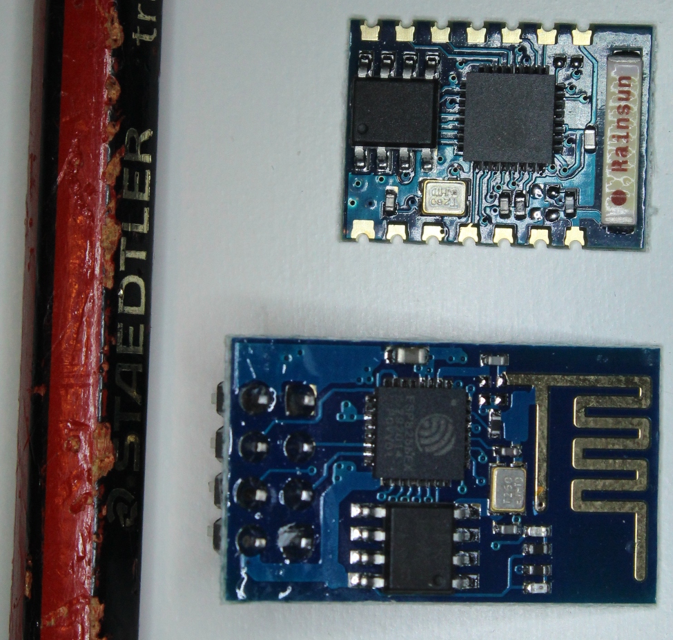
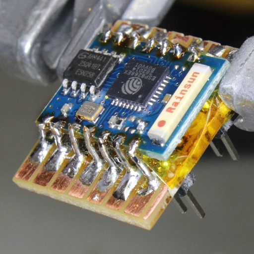
The ESP8266
The technology required to make this possible (at least from a hobbyist perspective) only became available late last year, in the form of the ESP8266. This remarkable module is tiny, has built in Wi-Fi, a programmable CPU able to control GPIO pins, and costs only about 3 dollars (including free shipping from China!)
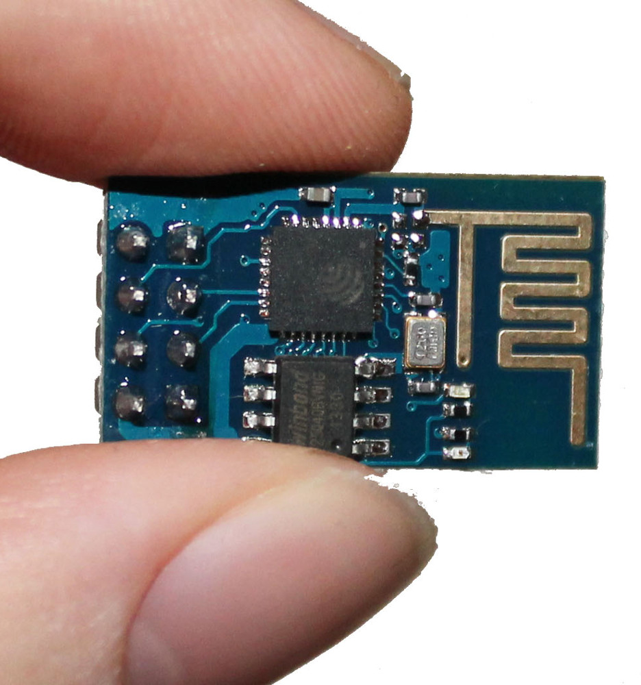
The drawback is that documentation is scarce – although this situation is gradually improving due to a few intrepid developers out there (refer links for details). It also does not run Linux like some other development boards, which means that you have a limited choice of development options (at least currently).
I initially started coding the wristband using Lua, which becomes possible by flashing the ESP8266 with the NodeMcu firmware, using ESPlorer. Although certainly an easy way to get started, in my case the results were flaky. I was constantly getting module resets, and wasn’t sure why. Memory also seemed to run out quite quickly. However, I may not have persevered enough, or the environment may have improved since then. So don’t let me put you off trying – here is a link to download my wristband_lua code.
As a result, with some trepidation, I moved onto using the Unofficial Development Kit by Mikhail Grigorev, which turned out be an excellent piece of work. It does require that you develop your code in C, which may not be to everyone’s taste. In my case, it is my preferred development language and so, quite a few hours later, I had ported across my wristband code into the “esphttpd” example provided in his SDK.
To my delight, this proved to be stable. Also, the serial bit-banging loops were running 250x times faster as measured on an oscilloscope – not essential for my application, but nonetheless satisfying.
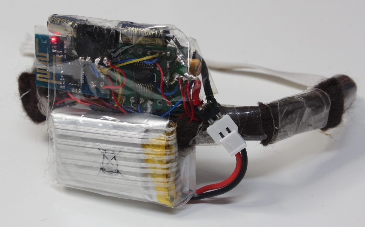
The First Prototype
The main objective was to find out how the multiple vibrating actuators would actually feel when on your arm. Was this a feasible approach to communicate a variety of different messages?
Continue reading →
 I have previously had two sets of PCBs made at ITEAD Studio, and been very happy with the results. Certainly their prices are good at $1 per 5cmx5cm board.
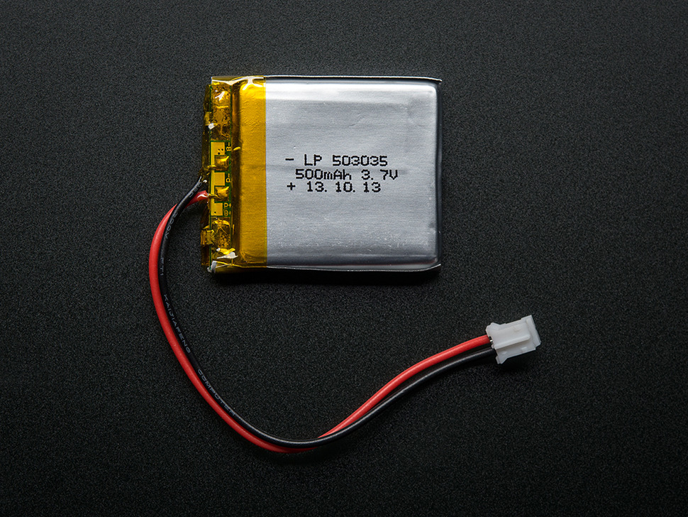 I designed the board with exactly the same dimensions as the Adafruit battery that I plan to use, since the board will sit on top of this battery (37mm x 30mm). The process for generating the correct files for an ITEAD Studio 2-layer board is quite simple, but you should follow the following steps once you have finished your design: Continue reading