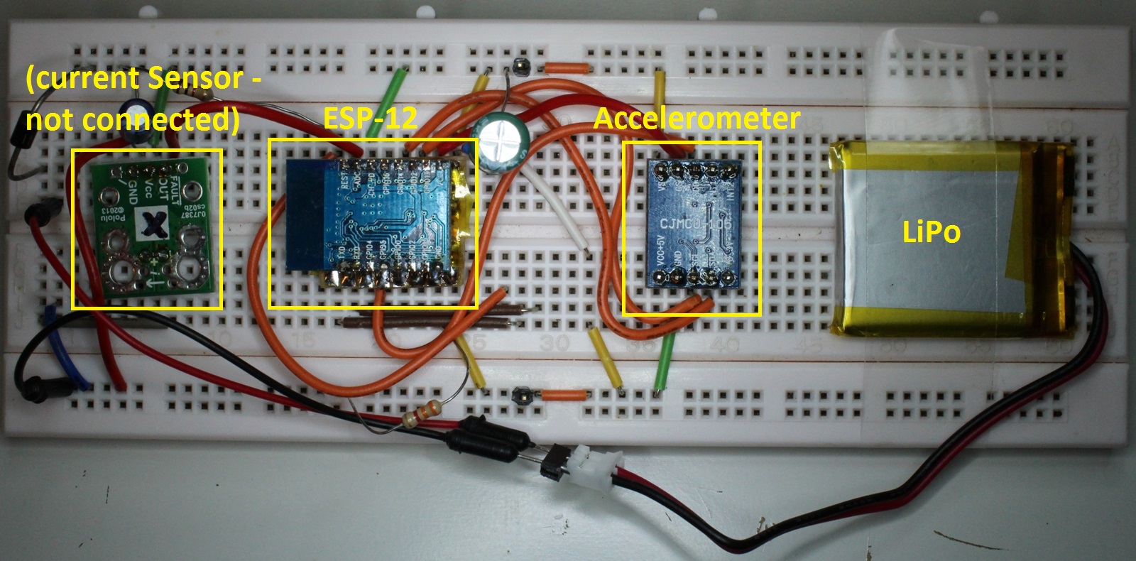
Over the last couple of weeks I have been sidetracked by another project – about which I’ll certainly share more details when it is done. The project has a requirement to stream readings to the Internet from an accelerometer (in a very small form factor), so I decided to pair one with an ESP8266.
 As I work more with the ESP8266, I am finding a common theme when using this chip.
On the one hand its low cost and extreme functionality in a very small package makes it a real game changer, and I was glad to see an article in Hackaday a week or so ago bringing this message to a wider audience. Essentially, the ESP8266 is not much more difficult to program than an Arduino, yet gives you a tiny, single-MCU solution with Wi-Fi included.
BUT, on the other hand, it can be really difficult to find good, clear information – at which point it suddenly becomes NOT an easy task to get something done. Although this situation is changing, it currently costs me more hours than I would have imagined to accomplish certain tasks.
I found myself in this wilderness recently after selecting the ADXL345 accelerometer chip, which I chose mainly because it works off 3.3V and because it has a good reputation. It also supports both SPI and I2C, which gives greater flexibility when interfacing to an MCU. So far, so good.
 This blog post details the different approaches I tried, and the challenges I faced. These were:
- I2C
- Hardware SPI
- Software SPI
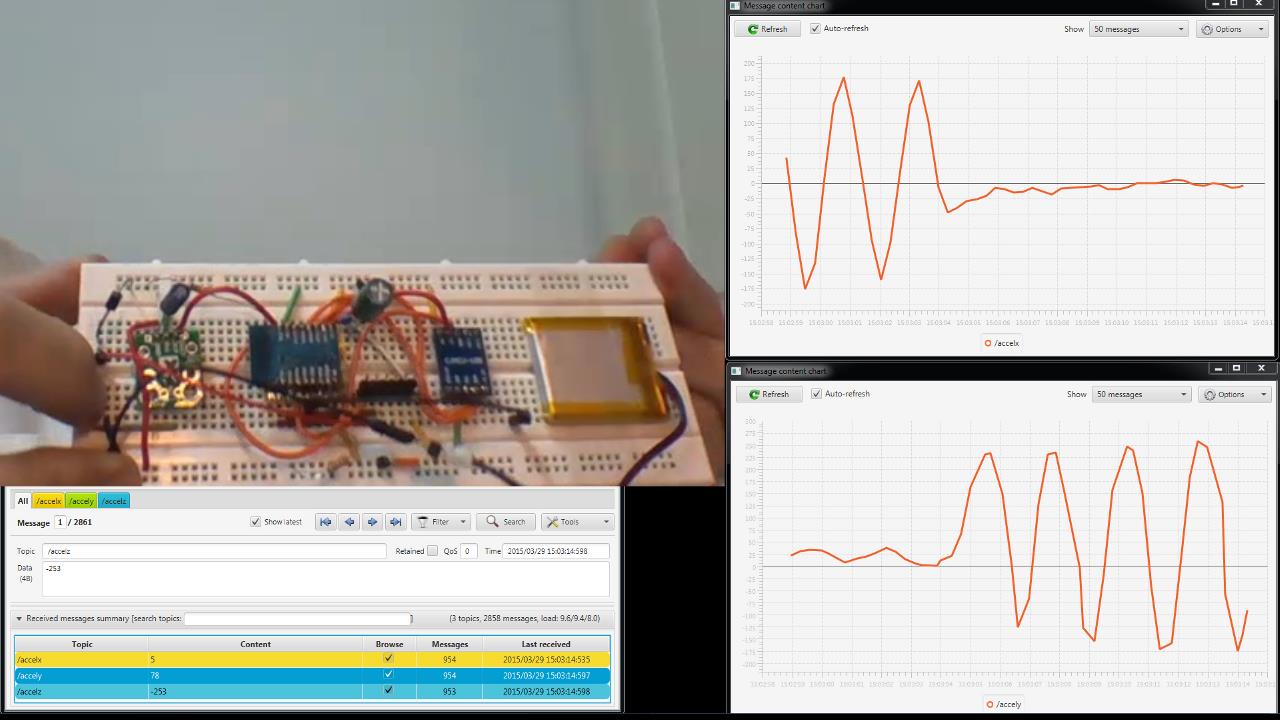
At the end I include a video showing a working ESP8266 (ESP-12 version, because I will later need an ADC) streaming accelerometer readings to an MQTT broker running on a Raspberry Pi, with results shown graphically on a PC, which is connecting to that broker.
I2C
At the outset I decided to use I2C because it only requires 2 wires and seems to be the most commonly supported protocol for (digital) accelerometers. Also, I believed that the I2C protocol was quite well supported by the ESP8266 SDK.
Unfortunately, when I started looking at the various SDK examples using I2C, it became apparent that:
- You would be required to call a bunch of i2c primitive functions called start, stop, check_ack, etc. Certainly not something that was going to be possible without diving into and understanding the i2c protocol. And , looking at the ADXL345 datasheet, it requires a “slave address” for i2c – yet the examples I was looking at did not implement this.
- Upon further examining the i2c primitive functions (in i2c.c), it appears that they are merely bit-banging GPIO ports (with software waits in between bits to get the correct timing – and i2C is not particularly fast at a maximum of 400kHz).

After spending many hours (in which I got to know i2c much better than I had ever intended!), I gave up. The real issue I found was that explanations of i2c are at a higher level, in which a driver takes care of the low level bit manipulation – not overly helpful when you are trying to debug lines by monitoring them going high or low. By the way, probably the nicest write-up I found (albeit for the Arduino) was here.
Hardware SPI
There are many comparisons of I2C and SPI. It boils down to: I2c is more complex, but more extendable. SPI is simpler, faster, but will tie up more I/O lines as the number of attached slave devices increases. The key aspect for me was that its simplicity would allow me to bit-bang the required protocol if the worst came to the worst. In fact, I realised that essentially I had already done this before when interfacing to a shift register for my wristband project.
Of course, it is always preferable to be able to offload a task from the processor to a hardware peripheral. I came across an interesting discussion on the ESP8266 forums on the topic of hardware SPI. Despite the discussion containing a couple of bizarre posts, I found that “TheLastMutt” and “picstart” have actually cracked it, but unfortunately not posted a final working set of code.
The real benefit here is the speed and the fact that bits are clocked out in the background, after the processor has moved on to other things. Here is my adaptation of their code:
hspi.c:
#include "driver/spi_register.h" // from IoT_Demo
#include "ets_sys.h"
#include "osapi.h"
#include "driver/uart.h"
#include "os_type.h"
#include "driver/gpio16.h" //from IoT_Demo
#include "gpio.h"

/*SPI number define*/
#define SPI 0
#define HSPI 1

#define lowByte(w) ((uint8_t) ((w) & 0xff))
#define highByte(w) ((uint8_t) ((w) >> 8))

void hspi_init()
{
// init the remap to HSPI
WRITE_PERI_REG(PERIPHS_IO_MUX, 0x105); //clear bit9
IN_FUNC_SELECT(PERIPHS_IO_MUX_MTCK_U, 2);//configure io to spi mode GPIO13 - HSPID MOSI
PIN_FUNC_SELECT(PERIPHS_IO_MUX_MTMS_U, 2);//configure io to spi mode GPIO14 - CLK
PIN_FUNC_SELECT(PERIPHS_IO_MUX_MTDO_U, 2);//configure io to spi mode GPIO15 - CS
//SET_PERI_REG_MASK(SPI_USER(HSPI), SPI_CS_SETUP | SPI_CS_HOLD | SPI_USR_MOSI); // use data only (no addr, no cmd, this is driven by DC pin)
SET_PERI_REG_MASK(SPI_USER(HSPI), SPI_USR_MOSI); // seems to work without SPI_CS_SETUP | SPI_CS_HOLD, not sure what they do
CLEAR_PERI_REG_MASK(SPI_USER(HSPI), SPI_FLASH_MODE | SPI_WR_BYTE_ORDER | SPI_USR_MISO | SPI_USR_ADDR | SPI_USR_COMMAND | SPI_USR_DUMMY); // big endian (MSB)
// SPI clock=CPU clock/2
WRITE_PERI_REG(SPI_CLOCK(HSPI),
((0 & SPI_CLKDIV_PRE) << SPI_CLKDIV_PRE_S) |
((1 & SPI_CLKCNT_N) << SPI_CLKCNT_N_S) |
((0 & SPI_CLKCNT_H) << SPI_CLKCNT_H_S) |
((1 & SPI_CLKCNT_L) << SPI_CLKCNT_L_S));

SET_PERI_REG_MASK(SPI_CTRL2(HSPI), (SPI_CK_OUT_HIGH_MODE<<SPI_CK_OUT_HIGH_MODE_S));
}

// routines to write 1,2,4 and 8 bytes
void hspiwrite(uint8_t data) {
while (READ_PERI_REG(SPI_CMD(HSPI))&SPI_USR); //waiting for spi module available
WRITE_PERI_REG(SPI_USER1(HSPI), (7 & SPI_USR_MOSI_BITLEN) << SPI_USR_MOSI_BITLEN_S); // 8 bits
WRITE_PERI_REG(SPI_W0(HSPI), (uint32)data); // the data to be sent
SET_PERI_REG_MASK(SPI_CMD(HSPI), SPI_USR); // send
}

void hspiwrite16(uint16_t w) {
while (READ_PERI_REG(SPI_CMD(HSPI))&SPI_USR); //waiting for spi module available
WRITE_PERI_REG(SPI_USER1(HSPI), (15 & SPI_USR_MOSI_BITLEN) << SPI_USR_MOSI_BITLEN_S); // 16 bits
WRITE_PERI_REG(SPI_W0(HSPI), lowByte(w) << 8 | highByte(w));
SET_PERI_REG_MASK(SPI_CMD(HSPI), SPI_USR); // send
}

void hspiwrite32(uint32_t w) {
while (READ_PERI_REG(SPI_CMD(HSPI))&SPI_USR); //waiting for spi module available
WRITE_PERI_REG(SPI_USER1(HSPI), (31 & SPI_USR_MOSI_BITLEN) << SPI_USR_MOSI_BITLEN_S); // 16 bits
WRITE_PERI_REG(SPI_W0(HSPI), w);
SET_PERI_REG_MASK(SPI_CMD(HSPI), SPI_USR); // send
}

void hspiwrite64(uint64_t w) {
while (READ_PERI_REG(SPI_CMD(HSPI))&SPI_USR); //waiting for spi module available
WRITE_PERI_REG(SPI_USER1(HSPI), (63 & SPI_USR_MOSI_BITLEN) << SPI_USR_MOSI_BITLEN_S); // 16 bits
WRITE_PERI_REG(SPI_W0(HSPI), w);
SET_PERI_REG_MASK(SPI_CMD(HSPI), SPI_USR); // send
}
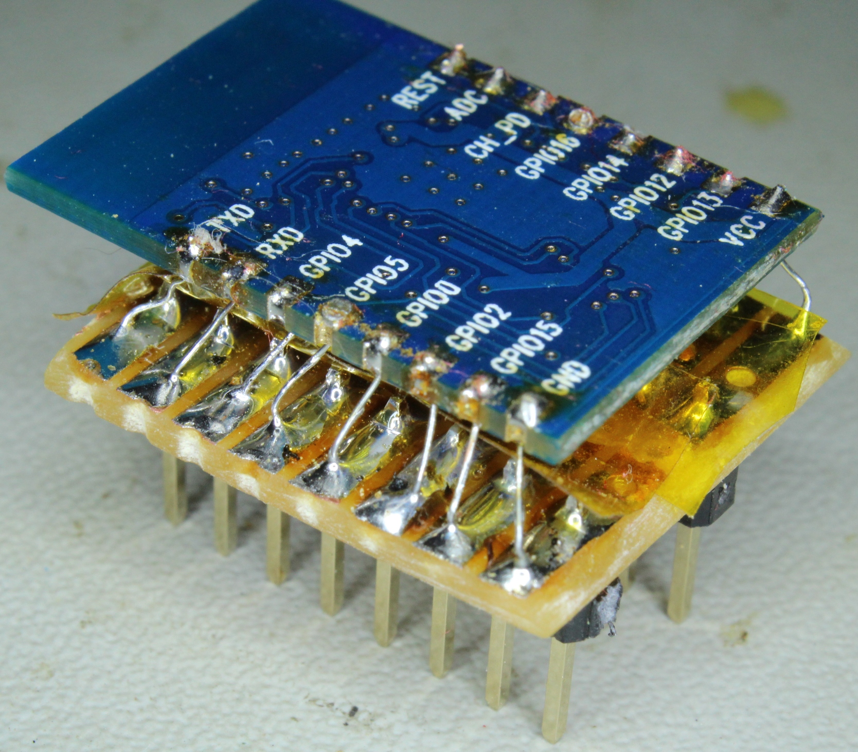
To use the hardware SPI, you will need to confirm the GPIO pins that you are using in hspi_init(), and then call the following from your code, as required:
hspi_init();

//example calls:
hspiwrite(0x04);
hspiwrite32(0xAAAAAAAA);
I shall definitely replace the bit-banging code in my wristband with the above, but unfortunately I ran into a problem in using it for the ADXL345. So, be warned that the above probably needs some more work, as I moved on without using it very much.
[update]: Found this: David explains more about the hardware SPI registers.
Software SPI (ADXL345 specific)
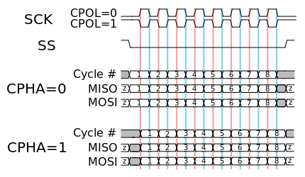 So, what was the obstacle that led me back to considering bit-banging SPI? Well, there are 4 different flavours of SPI, dependent on 2 factors:
- Clock Polarity (CPOL) – is it normally high or low in the period between transferring data bits?
- Clock Phase (CPHA) – is the data sampled on the rising or falling edge of the clock?
The most common form is CPOL=0, CPHA=0. The code in the previous section will work for this mode. But the ADXL345 requires CPOL=1 and CPHA=1, I believe to allow the same set of ADXL345 pins to do double duty for both I2C and SPI.
Sadly, as far as I can find, the ESP8266 does not seem to be able to do this mode (please correct me if you know otherwise). The only place on the internet that I could find anything was even less encouraging. If you take a look at the nodemcu firmware, you will find this commented out code for the CPOL=1 option:
//set clock polarity
// TODO: This doesn't work
//if (cpol == 1) {
// SET_PERI_REG_MASK(SPI_CTRL2(spi_no), (SPI_CK_OUT_HIGH_MODE<<SPI_CK_OUT_HIGH_MODE_S));
//} else {
// SET_PERI_REG_MASK(SPI_CTRL2(spi_no), (SPI_CK_OUT_LOW_MODE<<SPI_CK_OUT_LOW_MODE_S));
//}
[update 2016: This issue appears to have now been resolved with a later SDK as per Espressif]
Interesting… but to press on with a software SPI approach, which I based on reading the ADXL345 datasheet. All you need to do is generate:
- A one byte command, consisting of an ADXL345 command register, a read/write flag, and a multi-byte flag;
- Followed by one data byte, or multiple data bytes (if the multi-byte flag was set above). This is used to read all the x, y and z registers in “one go” to ensure consistency.
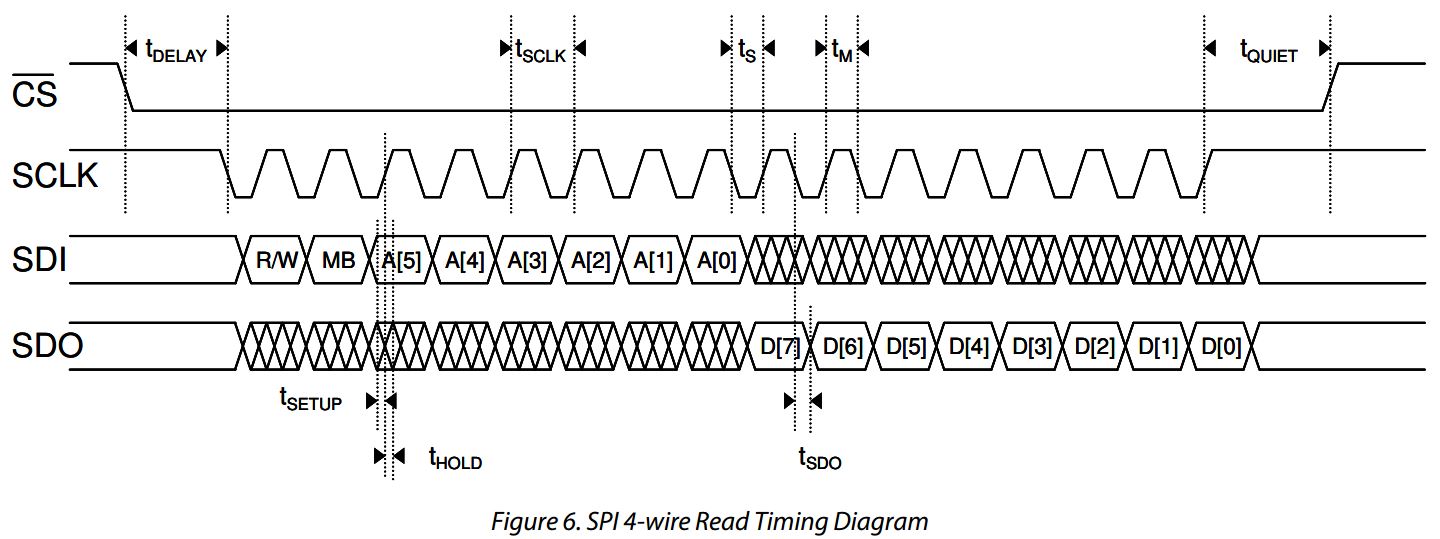 So, as examples:
1. To start the device measuring acceleration, you need to set a “measurement flag” by:
- 1st byte – specify the ADXL345_BW_RATE command register in bits 0..5, reset the write flag and multibyte flag to 0
- 2nd byte – send 00001000 to set the “measurement flag”
2. To read all the x, y and z registers in one go:
- 1st byte – specify the ADXL345_DATAX0 register in bits 0..5, set the read flag and multibyte flag to 1
- next 6 bytes – read the z,y,z (double byte) registers consecutively
I won’t list it here, but you can take a look at my code in this zip file (spi_lite.c, spi_lite.h and ADXL345.c plus ADXL345.h, which I adapted from the manufacturer’s code on github).
For the accelerometer demo, I am calling the spi_lite library as follows:
#include "driver/spi_lite.h"
ADXL345_Init();
sint16 x,y,z;
ADXL345_GetXyz(&x,&y,&z);
Because of the requirements for my project, I needed a local MQTT broker, which I installed on a Raspberry Pi. This was straightforward, so I won’t document this. You could look, for example, try here. I didn’t bother setting up security, as everything is on my internal network, so the process was even easier.
The results are shown graphically on a PC using mqtt-spy, about which I have posted before.
Enjoy the video! Although it is not exactly riveting viewing, it represents quite a lot of cool technology working together.
Great post! Are you actually using nodemcu here? If so, how are you running the demo code which is C and not Lua? Cheers!
No, I started off using Lua but ran into limitations (details here: wrist alert). So I use C now. Yes, there is a small learning curve at the start getting to know the ESP8266 SDK, but thereafter it is no harder than programming an Arduino.
This is great any chance you could post a link to the source?