A lot of the initial interest in the ESP8266 has been about using it as an add-on wifi board together with something like an Arduino. Now, in many situations this makes sense: leverage your skills and familiarity with your chosen MCU and its development environment, but add Wi-Fi capabilities using the ESP8266 simply and cheaply.
But what interests me more is what becomes possible when using the ESP8266 as a single solution for both processing and Wi-Fi. Nowhere is this more relevant than when size is a primary constraint. This is true of most wearable devices, but can often be the case for Internet of things (IoT) devices – particularly those that were never originally designed to be IoT enabled.
In this realm, it quickly becomes crystal clear that SMD technology is not just an option, but a prerequisite. Without it, even a very few discrete components demand more space than an entire ESP8266 board.
Unfortunately these tiny components are more difficult to work with than discretes, and generally a PCB is desirable to mount the components. However, I am finding that with magnification, flux and some patience, it is possible to build space-constrained prototype circuits on the fly.
 I will be posting a new project in
 3 weeks May that is a good demonstration of this, but for now here are a few glimpses to illustrate.
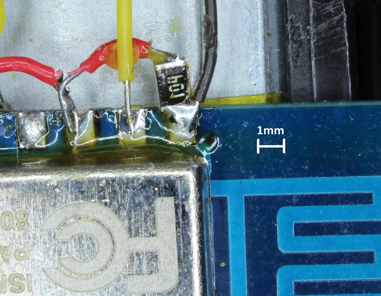
The first example is adding a 100nF capacitor as part of a start-up reset circuit. Here I have soldered an SMD part directly to the ESP-12 board reset pin. I was using an 0805 part, which at 1mm x 2mm takes up almost no additional space.
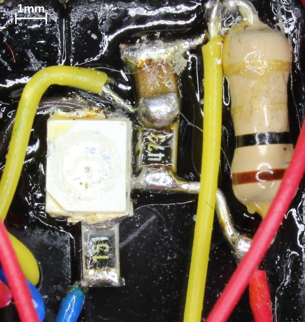
My second example is a circuit for measuring current. A discrete 1/4 watt resistor was used because of the requirement to carry the full current in series with the load. But, for my purposes, I wanted to smooth out the resultant noisy PWM-driven signal. So I used a low pass filter consisting of an SMD capacitor and resistor before sending on to the ADC of the ESP8266.
Also in the picture is an SMD led and current limiting resistor, surrounded by epoxy holding everything together.
There simply would not have been space for using the discrete equivalents.
(Looking at these magnified views, I really need to try and clean off all that flux residue…!)
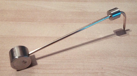 I am always interested in anything that promises to make small-scale soldering work easier, and so was intrigued by the “SMD beak”, a device built to hold down an SMD part while you solder it onto a PCB.
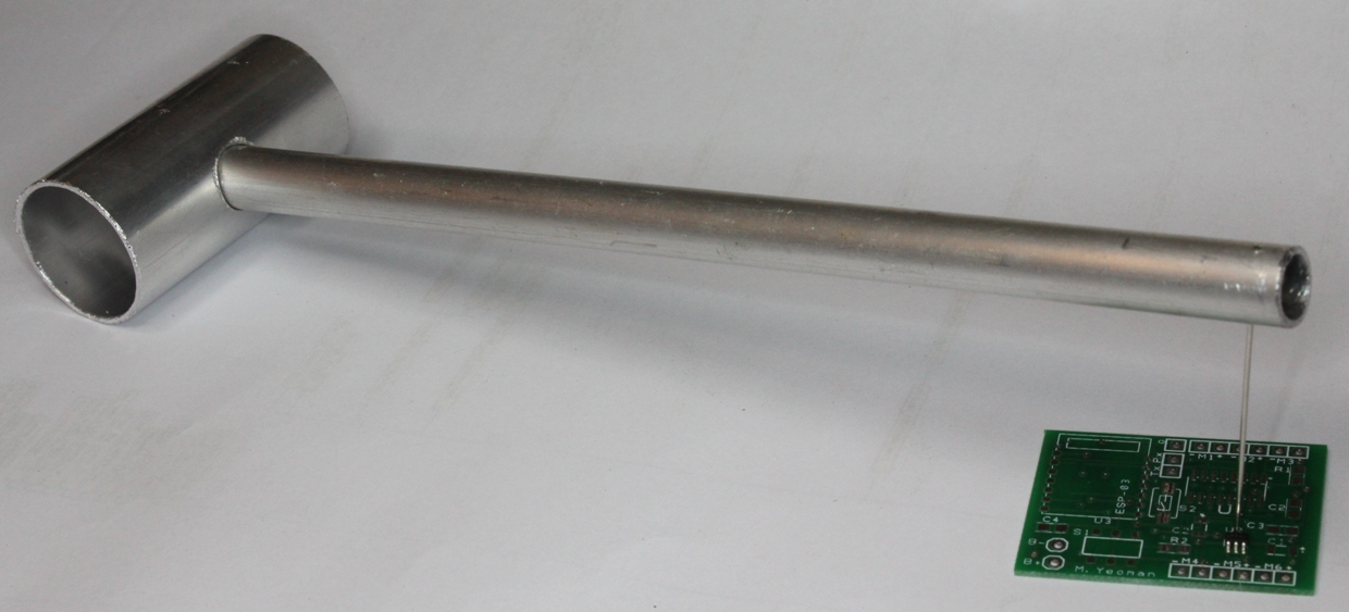
I decided to make my own. Although not nearly as stylish, it only took about 30 minutes to make (plus time for the epoxy to set).
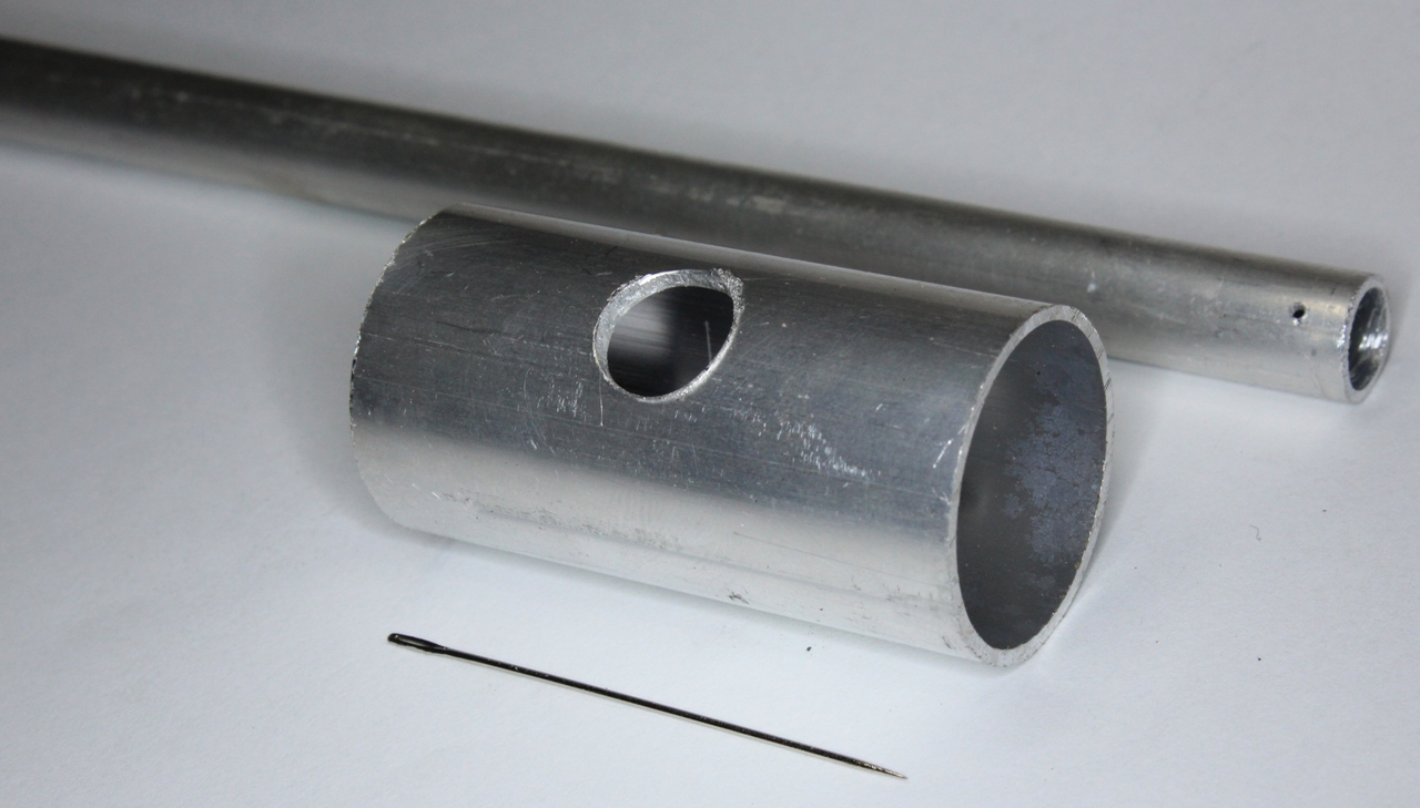 My version consists of 3 parts:
- 25mm aluminium tube, cut to 50mm
- 10mm aluminium tube, cut to 200mm
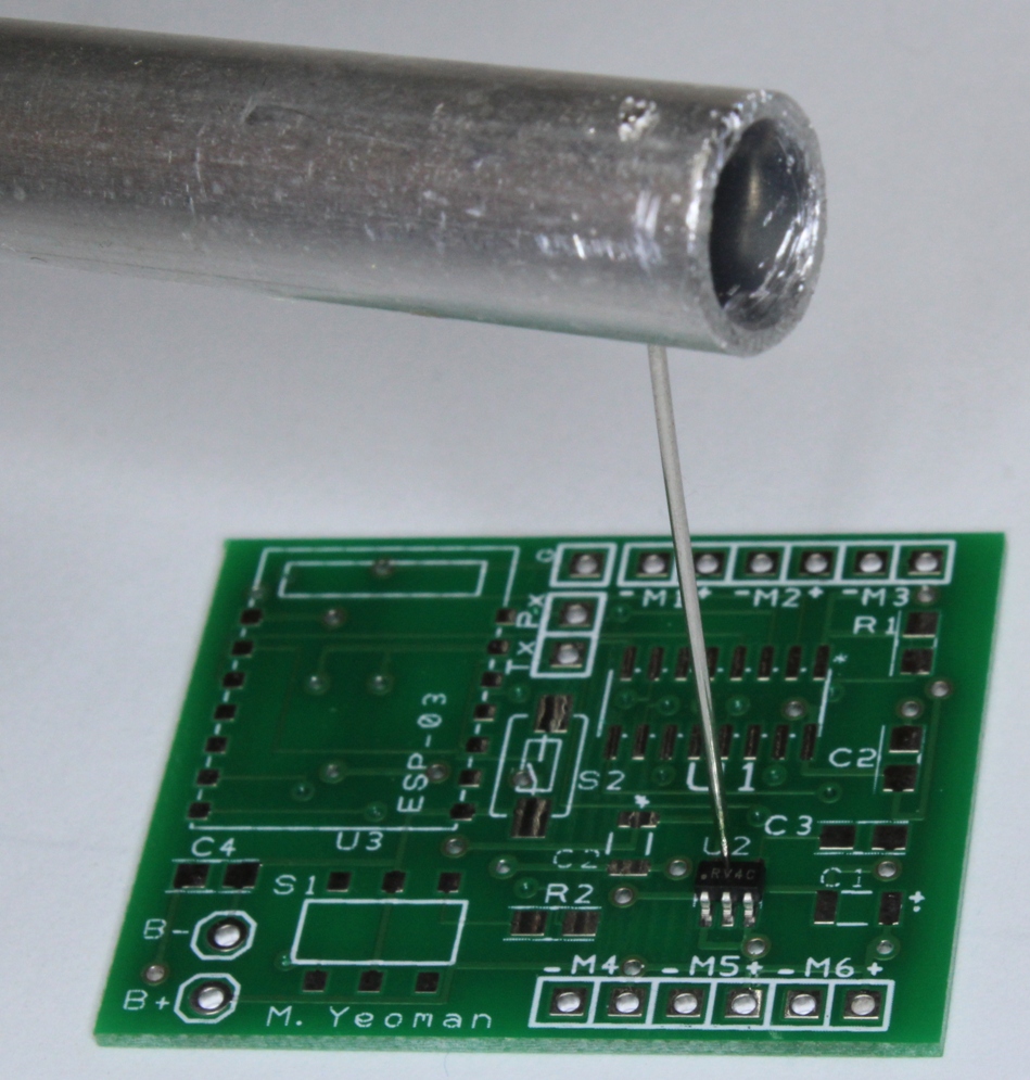
- Sewing needle
These are then simply epoxied together. The only potential limitation is that, being made of aluminium, the overall structure is quite light, so I will have to experiment to see if adding weight (e.g. fishing sinkers inside the tubes) is necessary.
The board in the picture is actually the one I described in a previous post, waiting until I have the time to assemble it!

