The ESP8266 and the art of the tiny

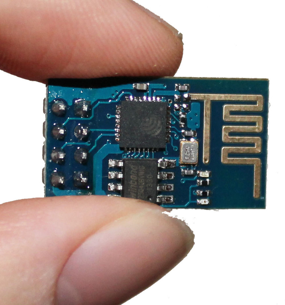
A lot of the initial interest in the ESP8266 has been about using it as an add-on wifi board together with something like an Arduino. Now, in many situations this makes sense: leverage your skills and familiarity with your chosen MCU and its development environment, but add Wi-Fi capabilities using the ESP8266 simply and cheaply.

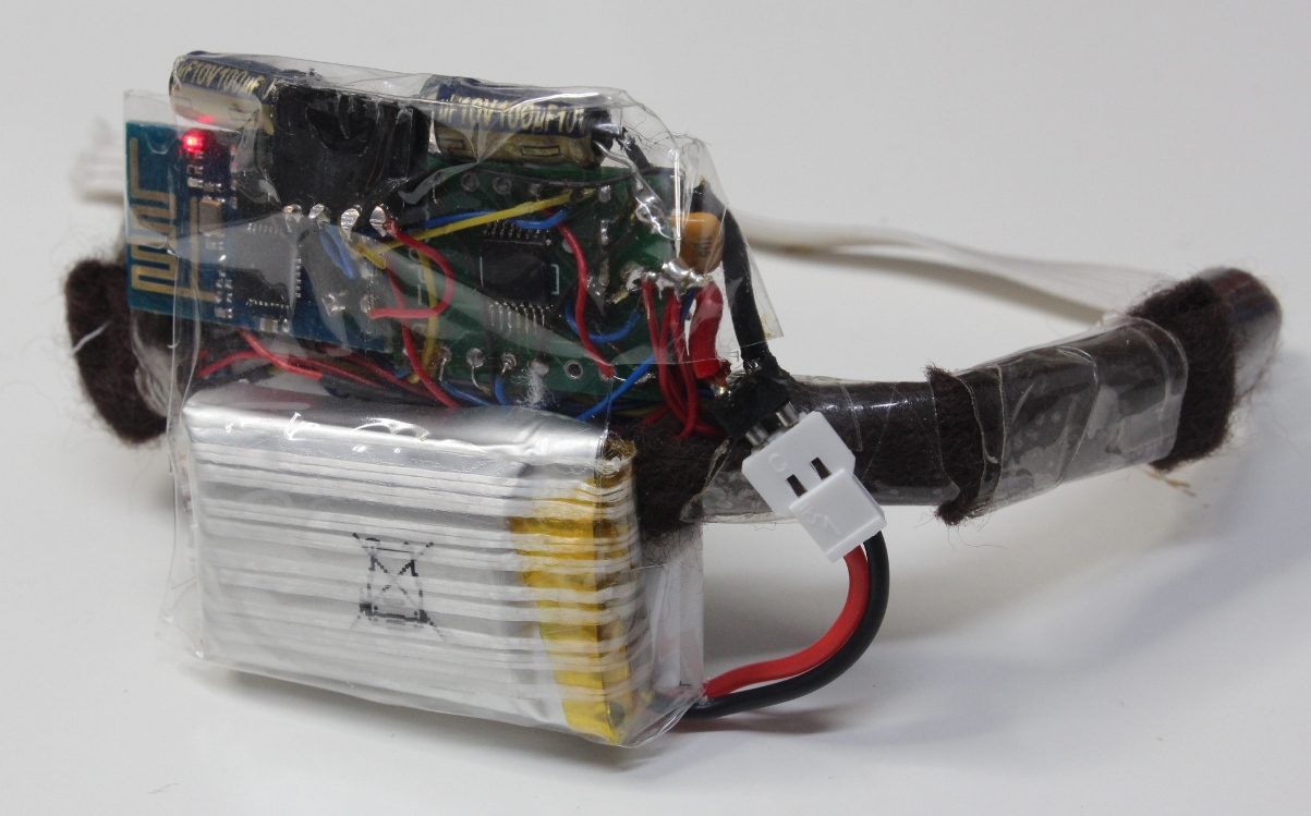
But what interests me more is what becomes possible when using the ESP8266 as a single solution for both processing and Wi-Fi. Nowhere is this more relevant than when size is a primary constraint. This is true of most wearable devices, but can often be the case for Internet of things (IoT) devices – particularly those that were never originally designed to be IoT enabled.

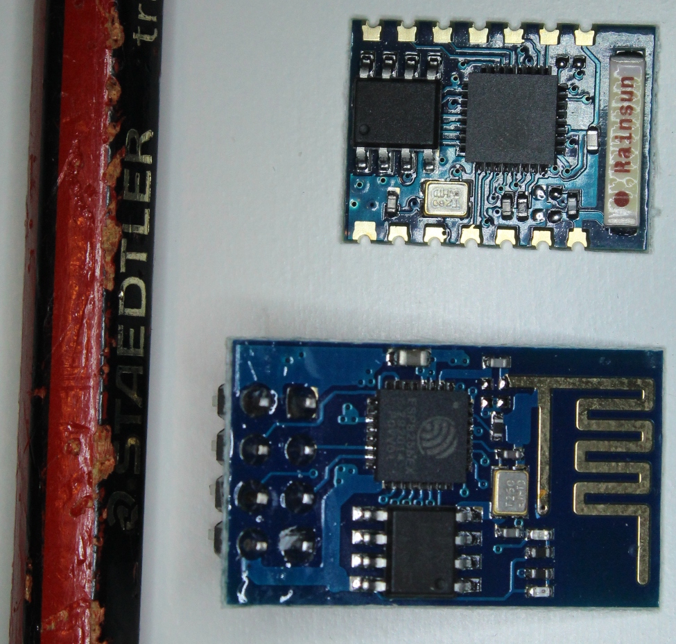
In this realm, it quickly becomes crystal clear that SMD technology is not just an option, but a prerequisite. Without it, even a very few discrete components demand more space than an entire ESP8266 board.

Unfortunately these tiny components are more difficult to work with than discretes, and generally a PCB is desirable to mount the components. However, I am finding that with magnification, flux and some patience, it is possible to build space-constrained prototype circuits on the fly.

IMG_4412mI will be posting a new project in 3 weeks May that is a good demonstration of this, but for now here are a few glimpses to illustrate.

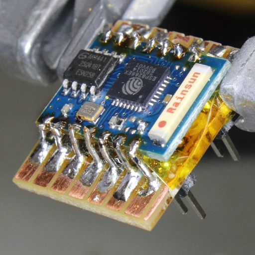
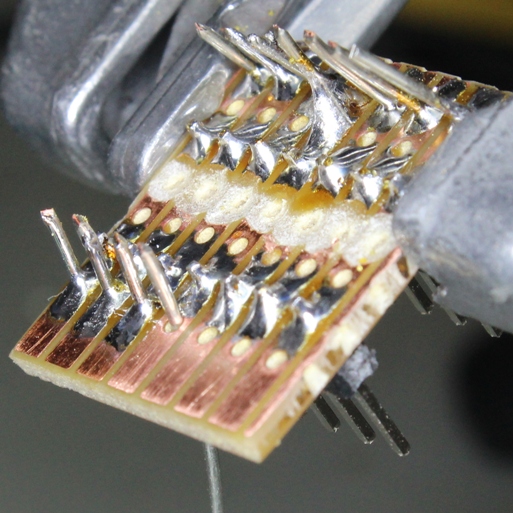
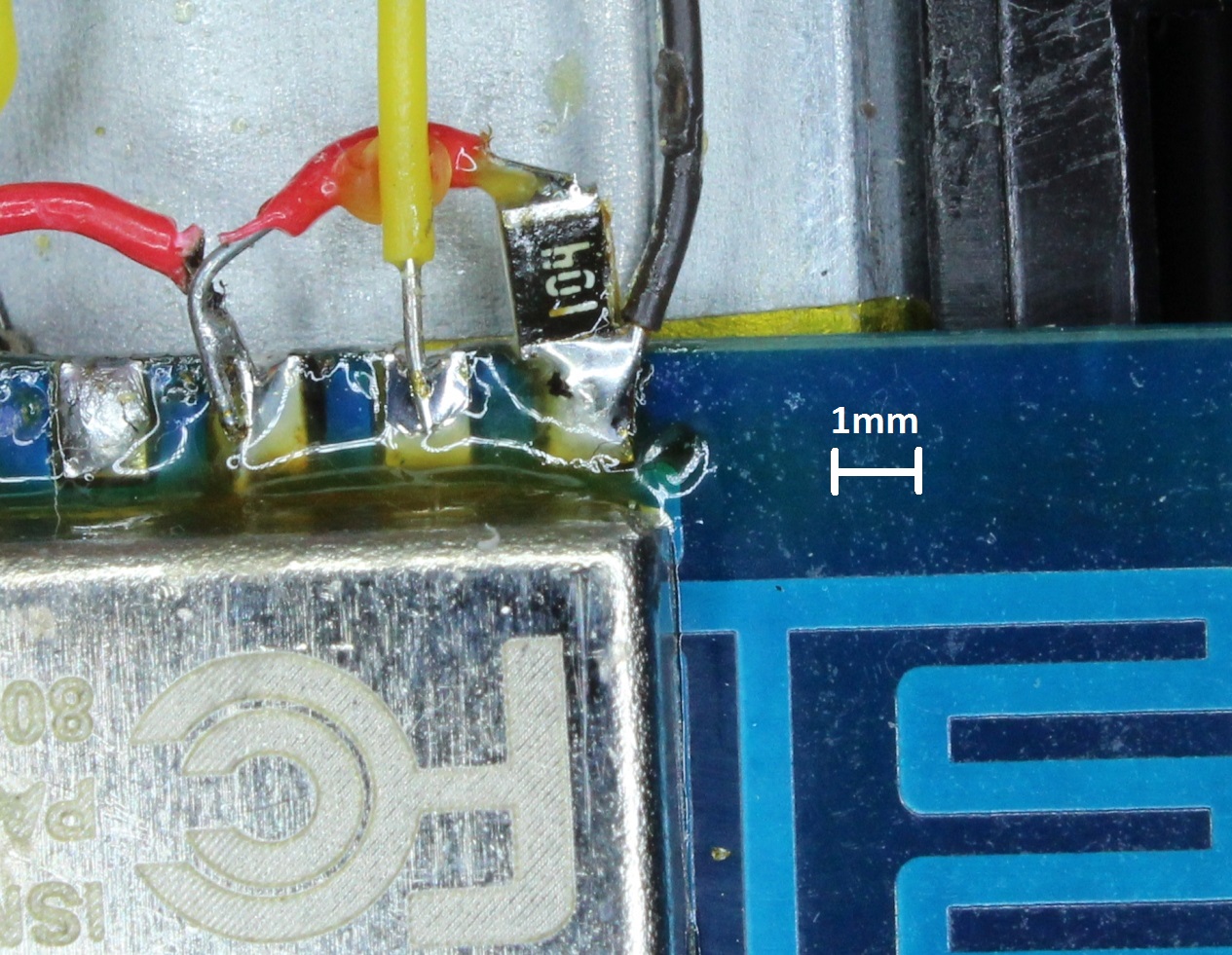
The first example is adding a 100nF capacitor as part of a start-up reset circuit. Here I have soldered an SMD part directly to the ESP-12 board reset pin. I was using an 0805 part, which at 1mm x 2mm takes up almost no additional space.
IMG_4410m

My second example is a circuit for measuring current. A discrete 1/4 watt resistor was used because of the requirement to carry the full current in series with the load. But, for my purposes, I wanted to smooth out the resultant noisy PWM-driven signal. So I used a low pass filter consisting of an SMD capacitor and resistor before sending on to the ADC of the ESP8266.

Also in the picture is an SMD led and current limiting resistor, surrounded by epoxy holding everything together.

There simply would not have been space for using the discrete equivalents.

(Looking at these magnified views, I really need to try and clean off all that flux residue…!)

SMD_Beak Continue reading

Reducing ESP8266 Power Consumption using deep sleep

[Update May 2016: for reducing power consumption of a NodeMCU board, see this post where I revisit the topic].

In my previous post, I mentioned that one of the reasons that I was excited about MQTT was because of its potential to allow power savings schemes on the ESP8266. The MQTT broker could asynchronously hold messages during the period that the ESP8266 was in a sleep cycle, to ensure that nothing is missed while dramatically reducing average power consumption.

This week I have hit a few obstacles, mainly due to the immaturity of current implementations of some of the latest MQTT qos (quality of service) features – at least that is what I suspect at this point. But more on that next week.

So, focusing on the ESP8266: my initial research had led me to believe that “deep sleep” mode was the way to go. Who can argue with using just 78μA during deep sleep?

To be able to implement deep sleep (without adding extra hardware to generate a wake-up signal), you need to link 2 pins on the ESP8266, as discussed here. Fortunately, the ESP-03 module has pads broken out on the PCB that you can join together. By linking these, you lose the ability to use GPIO16, but gain an automatic wake-up from deep sleep after the number of microseconds that you specify in the system_deep_sleep(time_in_us) call. You can understand better how this works by looking at the ESP-03 schematic.

To avoid any confusion, the pads to join are shown below:

ESP-03-rst1 Continue reading

“Haptic Bracelet” published by Hackaday… and working on the next version

It was fantastic to see my vibrating wristband appear on http://hackaday.com/2015/02/12/a-haptic-bracelet-for-physical-computing/

Brian Benchoff did a great job writing his article.

Meanwhile, I am working on my next prototype. The main goals are to:IMG_4268s

  1. Make the action of each vibration motor more specific. This will be done by eliminating the plastic backbone (which conducts vibrations). I will instead use a fabric band with compartments to keep components in the right place.
  2. Make everthing smaller by designing a pcb to hold all of the electronic components.
  3. Use the ESP-03 version of the ESP8266, as it is smaller and has more outputs that are broken out.
  4. Move beyond the web server / page demonstration to connect the device to a message source elsewhere on the web.

IMG_4272s

I have managed to get a newly arrived ESP-03 working on a breadboard, including properly latching the shift register during updates, as I mentioned I intended to do.IMG_4271s

With the previous ESP-01 version, I tried making an adapter to reuse the ESP8266, but it all went wrong when the solder flowed more than I intended. It then struck me that the modules are so cheap that it is not worth going to all the effort – just keep one permanently for breadboard prototyping.

IMG_4273s

I have been making extensive use of the SDK examples to work out what to do. But, when faced with a bunch of c modules and headers for the first time, it can be difficult to get an overview of how they interconnect and interrelate.

There must surely exist some good (and free) tools to generate these “call graphs“. After all, this capability is built into any compiler?

Continue reading

Vibrating Wristband Alert

Welcome to this first post on my blog. Over the years I have enjoyed following and using the work of many others across the Internet, so have decided to contribute my efforts to the community as well.

I have always had a passionate interest in electronics (refer to About), but these days it is very much a hobby. So, if you look around my site, you will notice placeholders for projects that I still plan to write up – sometime in between work and family life.

The Concept

I was motivated to develop a vibrating wristband communication device after reading “Enchanted Objects” by MIT Media Lab’s David Rose. In the book, he imagines a future based not around the “cold slab of glass” of our smartphone screen, but instead on “technology that can enhance our five senses and optimize our physical abilities – by accommodating and responding to the way we already operate in the world”.

IMG_3926s

As I planned my device, I drew up the following wish-list:

  1. The device should communicate with us in an immediate way that bypasses our usually overworked visual sense.
  2. The device should have multiple vibrating actuators to be able to deliver a richer message than can be achieved by using “Morse code” like on-off pulses to a single actuator.
  3. It should use Wi-Fi to connect directly to other devices over the internet. This is in contrast to almost any other similar device either available or being proposed. Of course, the use of Wi-Fi instead of BLE does mean a higher power consumption. But for this proof of concept, I wanted a device that was a “first class citizen”, not requiring tethering to a smartphone or other device. The power issue could be dealt with later, hopefully with sleep modes, advancing technology, etc.
  4. In keeping with the Internet of Things (IoT) ethos of ubiquity, the device needed to be low cost. This is particularly important for the wristband, because it is explicitly designed as a single function device, not to be all-in-one and consequently complex-to-use as seems to be the current trend.

The ESP8266

The technology required to make this possible (at least from a hobbyist perspective) only became available late last year, in the form of the ESP8266. This remarkable module is tiny, has built in Wi-Fi, a programmable CPU able to control GPIO pins, and costs only about 3 dollars (including free shipping from China!)

ESP8266

The drawback is that documentation is scarce – although this situation is gradually improving due to a few intrepid developers out there (refer links for details). It also does not run Linux like some other development boards, which means that you have a limited choice of development options (at least currently).

I initially started coding the wristband using Lua, which becomes possible by flashing the ESP8266 with the NodeMcu firmware, using ESPlorer. Although certainly an easy way to get started, in my case the results were flaky. I was constantly getting module resets, and wasn’t sure why. Memory also seemed to run out quite quickly. However, I may not have persevered enough, or the environment may have improved since then. So don’t let me put you off trying – here is a link to download my wristband_lua code.

As a result, with some trepidation, I moved onto using the Unofficial Development Kit by Mikhail Grigorev, which turned out be an excellent piece of work. It does require that you develop your code in C, which may not be to everyone’s taste. In my case, it is my preferred development language and so, quite a few hours later, I had ported across my wristband code into the “esphttpd” example provided in his SDK.

To my delight, this proved to be stable. Also, the serial bit-banging loops were running 250x times faster as measured on an oscilloscope – not essential for my application, but nonetheless satisfying.

The First Prototype

The main objective was to find out how the multiple vibrating actuators would actually feel when on your arm. Was this a feasible approach to communicate a variety of different messages?

Continue reading