IoT Container makes shopping easier

A frequently touted promise of IoT is to make your life easier by making everyday objects smarter. This has led to a slew of connected devices targeted at the consumer.

IoT clothes peg - is this your must-have device?
IoT clothes peg – is this really your must-have device?

I don’t know about you, but many of these products seem to be targeting a need that I didn’t realise I had, rather than being genuinely useful.

Instead of developing yet another solution in search of a problem, I decided to address a very real need in our household. Due to busy schedules, I often find myself in the supermarket on the way home from work, trying to remember what food needs buying. It seems that I am not the only one experiencing this situation. Compounding this problem is that my teenage sons can consume a LOT, but what they are consuming at any point in time is erratic and difficult to predict.

IMG_0419s
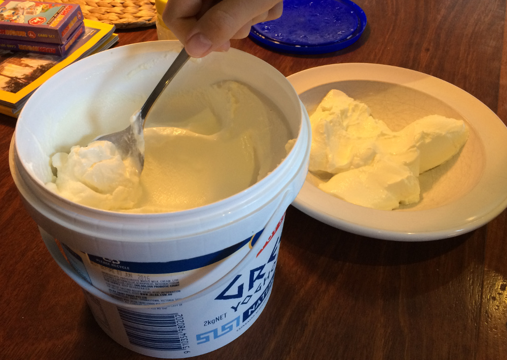
As an example, we recently went through a (relatively healthy) phase of consuming Greek yoghurt. To keep up with demand, we standardised on buying a 2kg (4.4lbs) tub – but only one tub at a time because of the space it occupies in the fridge. Unless I have recently eaten some, it becomes guesswork as to whether or not to replenish. And, in case you’re wondering, forget about getting my sons to proactively flag that anything is running out.

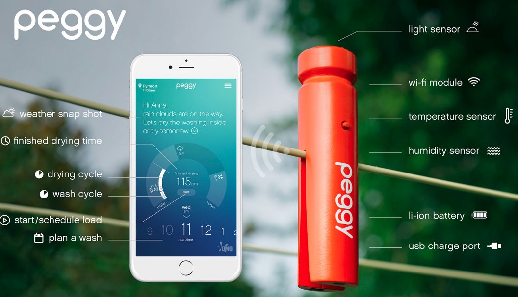
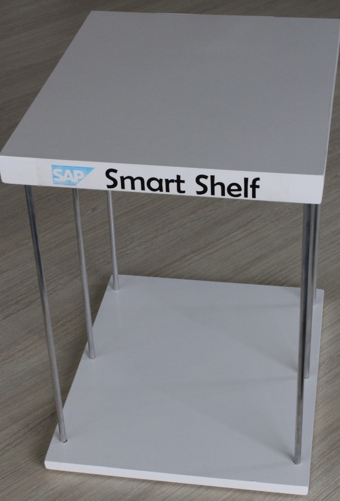
Time to hack together something to automatically give me that information, whenever and wherever I needed it. Yes, I could wait for a product (most likely at substantial cost) to be available like the smart mat demonstrated at CES 2016… but what would be the fun in that?

adio2
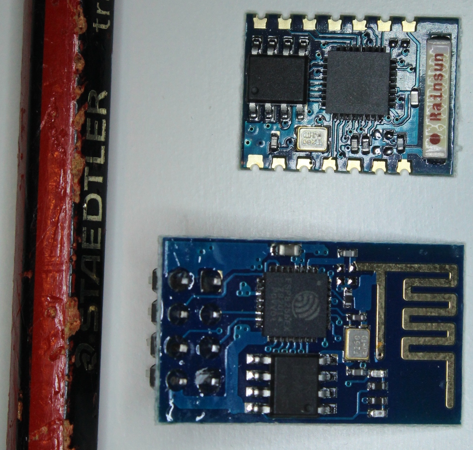
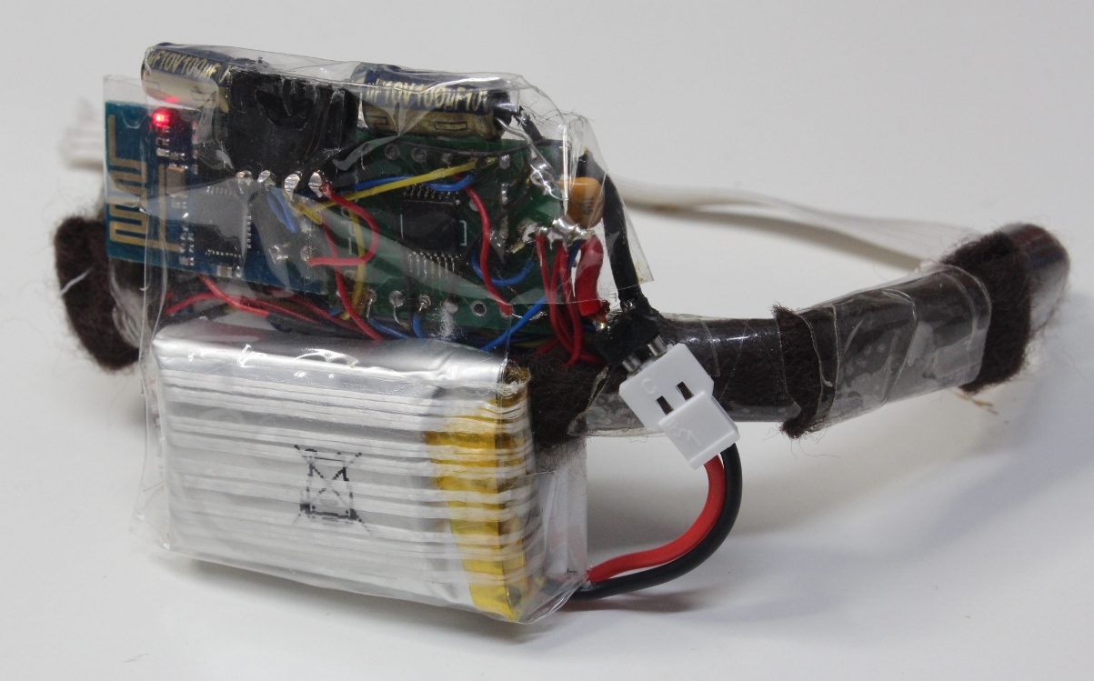
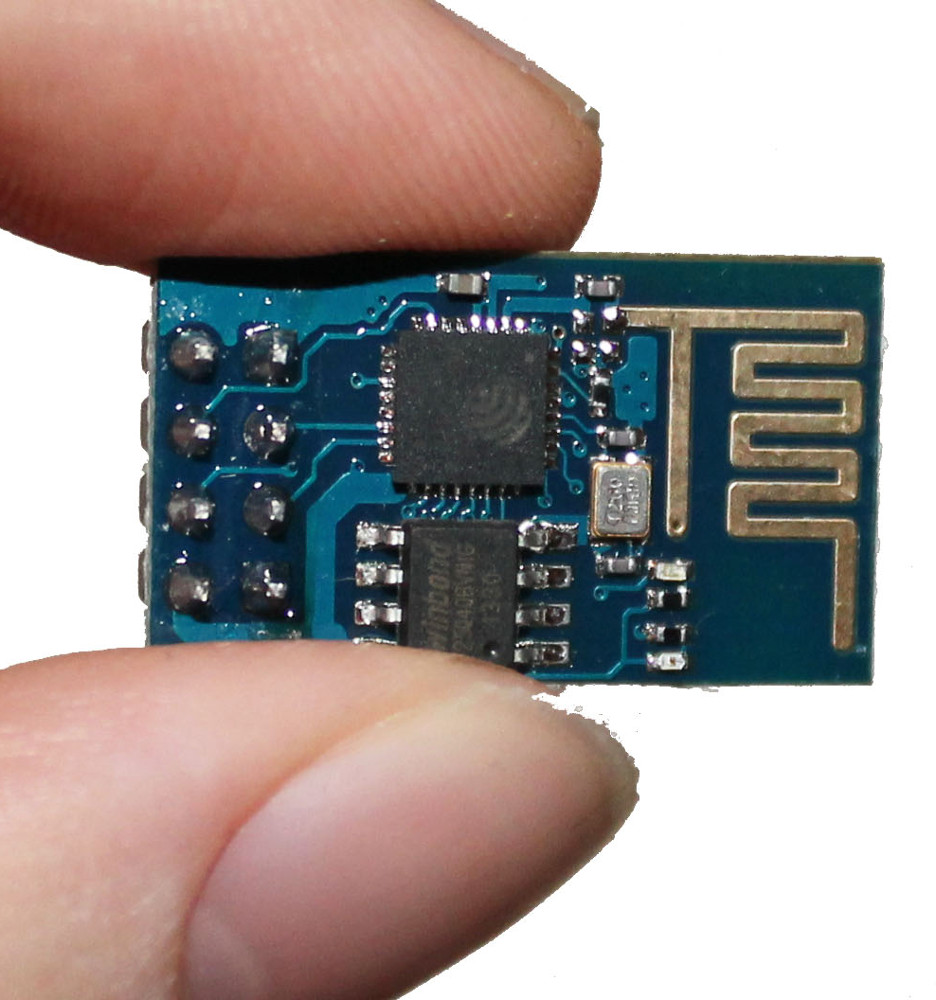
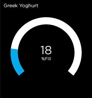
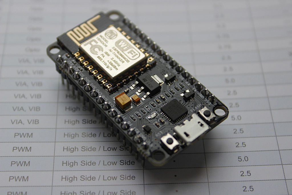
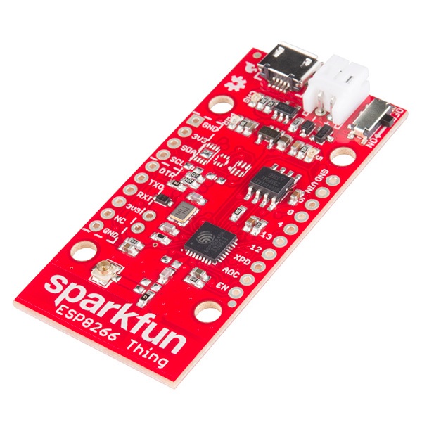
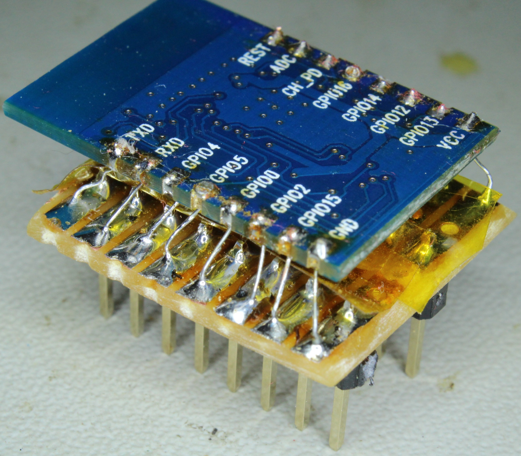
Fortunately, with a NodeMCU, some clever (at least I think so) Arduino code, the Adafruit IO cloud platform and a weight sensor, we have all the ingredients to build a device that will let us check the current yoghurt level on a smartphone at any time, and also send a text alert if supplies hit a critical level, all at a very low cost (excluding your time of course).

You can experience a live version of my yoghurt monitor here.

As you read on, keep in mind that this approach could be generalised to monitor any container. Also, the strategy would be to have multiple of these or similar devices. With many devices, it would be annoying to receive alerts every time something needs replenishing; instead, I imagine that they would update an automated shopping list, ready for when you are in the store.

IMG_5313m Continue reading

Running NodeMCU on a battery: ESP8266 low power consumption revisited

Over the last year I have standardised on the ESP8266 for all my small IoT projects. Its low price, ease of use (now that the Arduino IDE is available), tiny size and built in Wi-Fi makes it a compelling option.

Using Wi-Fi is a convenient way to link your newly created IoT device into your existing IT infrastructure – including cloud services – but it also has a drawback. Wi-Fi’s demand for power usually makes battery operation impractical for any real deployment. I have been able to get around this issue for most of my projects (e.g. the train and the smart shelf described on this blog) because they are for demonstration purposes only, requiring the battery to last no longer than a few hours.

Nevertheless, it is possible to put the ESP8266 into deep sleep and wake up periodically to check and activate Wi-Fi only when required. This would suit a scenario in which an IoT sensor sends relatively infrequent one way traffic (i.e. where real time control of the device is not needed).  I wrote about the ESP8266 deep sleep option more than a year ago, but have not explored it any more until recently, when exactly such a project arose.

NodeMCUThe other thing that I have done over the last year is to standardise on using the NodeMCU (hardware, not the LUA software). Especially when rolling out multiple small projects, it is immensely convenient to be able to plug a device into a USB port and just program it (automatically without having to wire up serial pins and then get the correct pins tied high / low for flashing / running). With no need to worry about providing 3.3V power, adding capacitors to prevent the ESP8266 power spikes from causing instability, or adding a resistor + cap for a power-on reset. No need to scale down the ADC input to 1V or to add my own test led… and all of this in a breadboard friendly package.

Also, just to be clear for those who may wish to follow along, I always use the “second generation” NodeMCU known as v2. The different versions are described here and I agree with that poster – i.e. don’t buy the v3 variant because its larger size means that it leaves no free breadboard holes on either side.

Unfortunately, with all this added convenience comes the drawback of added power consumption, which continues even when the ESP8266 is in deep sleep.

I measured 18mA to the NodeMCU board while the ESP8266 was in deep sleep mode – orders of magnitude more power hungry than I was looking for.

So for my iot-container project, I sought to retain the convenience of using the NodeMCU, but to address its power consumption shortcomings to allow battery operation.

Read further to hear what I did. Continue reading

ESP8266 Smart Shelf – Part 2 (NodeMCU + Arduino IDE)

In Part 1, I introduced the Smart Shelf concept, the sensor used, and the web page for displaying real-time updates.

Since then, I have also created a short video to demonstrate the project:

Part 1 explained how I used the Sparkfun ESP8266 Thing and the C SDK. For reliability reasons (in my case, when presenting / demonstrating in front of a live audience you ideally want things to work!), I have always preferred to use the C SDK, especially after the problems I experienced with Lua causing frequent reboots when I tried that approach a year ago.

IMG_4663mBut with the arrival earlier this year of the Arduino IDE, there is now a compelling alternative, which seems to work well (based on my limited experiments). So, as illustrated in this post, if you are an Arduino user, my view is that connecting a NodeMCU board and programming using the Arduino IDE is no more difficult than developing using an official Arduino board. The advantage is that you get built-in Wi-Fi, a smaller form factor and all this at a fraction of the cost. So for many applications, using an ESP8266 dev board like the NodeMCU might be the approach to consider first. Continue reading

ESP8266 Smart Shelf – Part 1

ESP8266 Dev Boards

I have realised, after spending some time building small projects using the ESP-01, ESP-03 and ESP-12 modules running off battery power, that it can be quite time consuming and tedious to build the necessary power supply circuit and wire up serial connectors each time. Also, where space is not critical (unlike in my train project), it becomes quite compelling to consider dev boards that integrate an ESP8266, together with other features, in an-easy to use (bread-boardable) form factor.

This is even more the case if you look at the falling prices of, for example, the NodeMCU board on AliExpress, You are not likely to be able to build your own equivalent at a lower cost, even discounting the time it would take.

In my type of interactive projects (where the ESP8266 cannot be put into deep sleep for extended periods), operating off battery power realistically means using LiPo/LiIon. As a result, I found myself having to disconnect the battery, attach it to a LiPo charger and then reconnect for every charge cycle.

Sparkfun ESP8266 Thing

This is when I saw that the Sparkfun ESP8266 Thing “includes a LiPo charger, power supply, and all of the other supporting circuitry”. Very convenient for what I had in mind…

But before I get to that, I want to be clear that the Sparkfun ESP8266 Thing is actually not my favourite module for the following reasons:

  • It is relatively expensive (more than 5 times the price of one of those NodeMCU boards listed above, including shipping)
  • Programming is not done neatly via the USB port like in the NodeMCU, so requires an additional 3.3V FTDI USB converter (or equivalent).
  • Unfortunately, the serial programming lines interfere with debugging via the serial port after programming, which requires that you install terminal software (e.g. RealTerm) that can disable toggling the DTR line, as described in the Sparkfun Hookup Guide. I have not yet tried the Adafruit Huzzah, but it does not appear to have this problem, although requires you to fiddle about with buttons to get into programming mode. In contrast, the NodeMCU board simply handles (transparently in the background) toggling GPIO0 low for a programming cycle.

It is worth noting that Sparkfun’s newer ESP8266 Thing – Dev Board fixes these issues (other than the price) – but then does not include a LiPo charger!

It would be interesting to find an inexpensive LiPo charger/management board that one could pair with a NodeMCU, if anyone knows of such a thing?

Smart Shelf Concept

Continue reading

A “Thomas” toy train joins the Internet-of-Things

I am intrigued by the notion put forward by David Rose (seen here presenting at TEDx) of “putting magic in the mundane – that is, having ordinary items that can do extraordinary things”.

I find compelling the notion that for everyday activities there will be a swing in popularity away from having to interact with complex abstract worlds behind glass screens toward a more “authentic” physical experience, for which we humans are so well adapted. But this shift will only be made possible by means of even more advanced technology – able to hide its own complexity.

This month the popular “Thomas the Tank Engine” toy celebrates its 70 anniversary. As a fun project, what could be more appropriate than to bring this traditional toy into the age of IoT, while preserving its physical appearance and simple charm?

For a short overview / teaser, watch the following video (be sure to select HD):

[youtube=https://youtu.be/-o6LYynn95E?hd=1&rel=0]

Inevitably there will be those who see this and ask “why?”

The short answer is that, as Hackaday believes,  “why” is the wrong question.

A longer answer is that the train is simply BETTER when you can control its speed (remotely over wi-fi), more consistent to operate, especially at low speeds because of an auto “throttle-boost” that kicks in when the accelerometer senses that the train is going uphill, and more user-friendly with remote monitoring of the battery state.

And if you need still more justification, the Train appeared this week at a trade exhibition as a source of IoT data to demonstrate business software (go to YouTube here if you are interested, where one of my colleagues explains).

The main challenge was to be able to fit the required electronics into an existing form factor. As it transpired, the toy train was a lot more compact than I had anticipated. I had to undertake some delicate “surgery” to free up space underneath the train and behind the front face, but this was done in a way that a casual observer would not notice.

Follow the link to a full write-up to discover more of the details:

Continue reading ->

The ESP8266 and the art of the tiny

A lot of the initial interest in the ESP8266 has been about using it as an add-on wifi board together with something like an Arduino. Now, in many situations this makes sense: leverage your skills and familiarity with your chosen MCU and its development environment, but add Wi-Fi capabilities using the ESP8266 simply and cheaply.

But what interests me more is what becomes possible when using the ESP8266 as a single solution for both processing and Wi-Fi. Nowhere is this more relevant than when size is a primary constraint. This is true of most wearable devices, but can often be the case for Internet of things (IoT) devices – particularly those that were never originally designed to be IoT enabled.

In this realm, it quickly becomes crystal clear that SMD technology is not just an option, but a prerequisite. Without it, even a very few discrete components demand more space than an entire ESP8266 board.

Unfortunately these tiny components are more difficult to work with than discretes, and generally a PCB is desirable to mount the components. However, I am finding that with magnification, flux and some patience, it is possible to build space-constrained prototype circuits on the fly.

IMG_4412mI will be posting a new project in 3 weeks May that is a good demonstration of this, but for now here are a few glimpses to illustrate.

The first example is adding a 100nF capacitor as part of a start-up reset circuit. Here I have soldered an SMD part directly to the ESP-12 board reset pin. I was using an 0805 part, which at 1mm x 2mm takes up almost no additional space.
IMG_4410m

My second example is a circuit for measuring current. A discrete 1/4 watt resistor was used because of the requirement to carry the full current in series with the load. But, for my purposes, I wanted to smooth out the resultant noisy PWM-driven signal. So I used a low pass filter consisting of an SMD capacitor and resistor before sending on to the ADC of the ESP8266.

Also in the picture is an SMD led and current limiting resistor, surrounded by epoxy holding everything together.

There simply would not have been space for using the discrete equivalents.

(Looking at these magnified views, I really need to try and clean off all that flux residue…!)

SMD_Beak Continue reading

ESP8266 and IoT: Streaming serial accelerometer data via MQTT

mqtt-accel

Over the last couple of weeks I have been sidetracked by another project – about which I’ll certainly share more details when it is done. The project has a requirement to stream readings to the Internet from an accelerometer (in a very small form factor), so I decided to pair one with an ESP8266.

IMG_4377As I work more with the ESP8266, I am finding a common theme when using this chip.

On the one hand its low cost and extreme functionality in a very small package makes it a real game changer, and I was glad to see an article in Hackaday a week or so ago bringing this message to a wider audience. Essentially, the ESP8266 is not much more difficult to program than an Arduino, yet gives you a tiny, single-MCU solution with Wi-Fi included.

BUT, on the other hand, it can be really difficult to find good, clear information – at which point it suddenly becomes NOT an easy task to get something done. Although this situation is changing, it currently costs me more hours than I would have imagined to accomplish certain tasks.

I found myself in this wilderness recently after selecting the ADXL345 accelerometer chip, which I chose mainly because it works off 3.3V and because it has a good reputation. It also supports both SPI and I2C, which gives greater flexibility when interfacing to an MCU. So far, so good.

IMG_4378This blog post details the different approaches I tried, and the challenges I faced. These were:

  • I2C
  • Hardware SPI
  • Software SPI

At the end I include a video showing a working ESP8266 (ESP-12 version, because I will later need an ADC) streaming accelerometer readings to an MQTT broker running on a Raspberry Pi, with results shown graphically on a PC, which is connecting to that broker.

Continue reading

Investigating MQTT persistence in an IOT protocol on the ESP8266

One of the most important reasons that I considered using MQTT for my haptic wristband project was because of its ability to handle devices that are intermittently connected. IOT devices, even if nominally switched on, may at any given time be unavailable due to sleep modes (even although this direction did not prove as promising on the ESP8266 for my application as I’d initially hoped), or simply because the device has temporarily lost Wi-Fi connectivity.

MQTTInspector_s
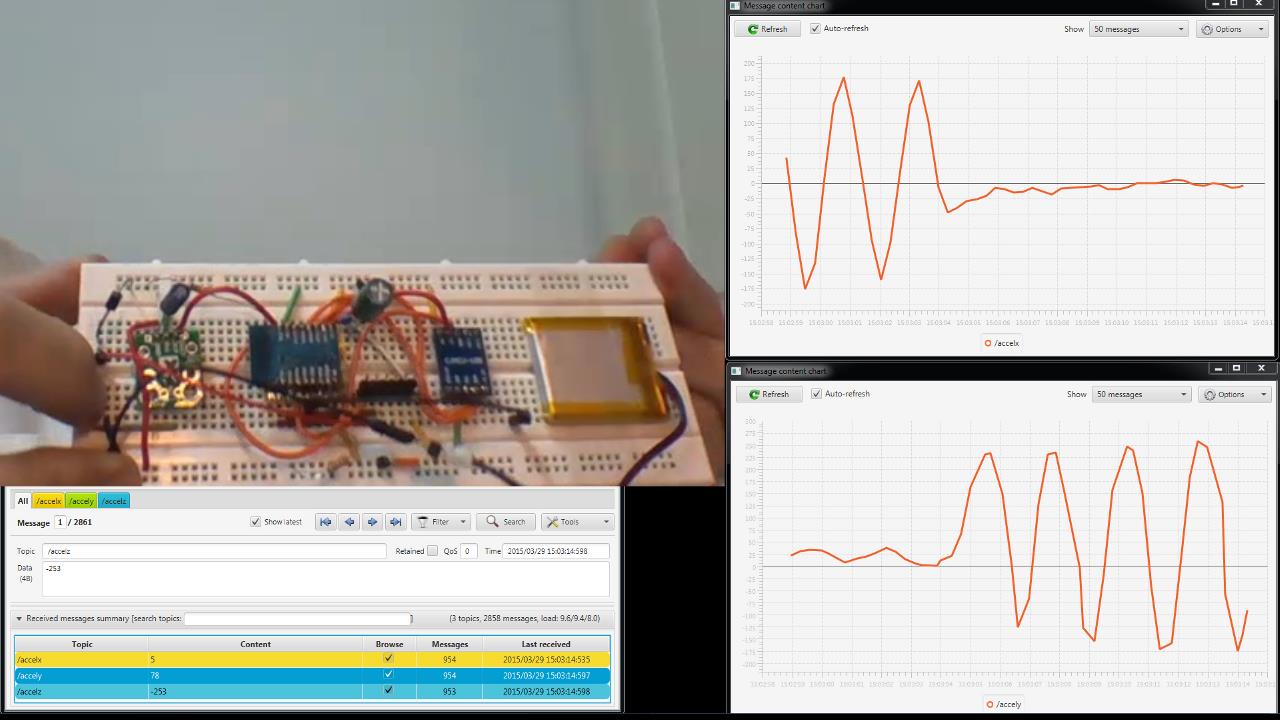
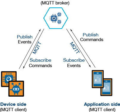
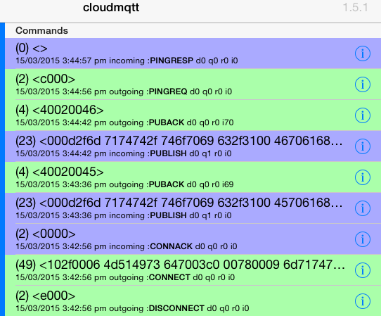
Whatever the cause of disruption, the MQTT architecture provides for the broker to store any important messages (i.e. those flagged with high qos or “quality of service”) to be later delivered to a client that had been previously subscribed, also with high qos, but is at that point in time disconnected.

For my project this is crucial. I have always envisaged my wristband to be an additional “priority” channel to cut through the barrier of noise created by the visual overload of our multiple screens, through the beeps and buzzes representing emails, meeting requests, tweets, texts, phone calls and missed calls – which are themselves competing for (hopefully) the majority of your attention directed at real people and real objects around you as you do your job and live your life!

Therefore, as a device that handles relatively few but very important notifications, a missed message is unacceptable.

Unfortunately, as I hinted at last week, I struggled to get this MQTT mechanism to work. The main problem I was having was that I was not sure where the fault lay – and even wondered if I was misunderstanding the way that MQTT should work. I began to suspect that the free MQTT broker that I was using did not support this more advanced behaviour. As it transpired, and thanks to some timely help from Carl at CloudMQTT support, the MQTT broker turned out to be fine – it was both the ESP8266 client and the MQTT test software that I was using that were dropping the ball.

After wading through many documents on the web, I also realised that this whole area of MQTT persistence is quite confusing and not well explained from the point of view of someone actually wanting to make use of it. So, in this post, I aim to first explain how persistence should work, and then afterwards provide all the details for someone to actually try it out for themselves. Along the way I also discover a couple of great new products. Continue reading

Investigating MQTT as an “IoT protocol” for the ESP8266 wristband

I have recently had a rethink about how I will link my wristband to an alert source.

To demo my first prototype, I hosted a web page on the ESP8266 device itself. Selecting a button on the web page posted a value, which activated the chosen vibration pattern. This is a very convenient way to demo the concept, but, in the real world it has some significant drawbacks.

The first drawback is that the whole submit / refresh cycle of a web page is not particularly fast, which also probably means that the web server on the ESP8266 is having to do a relatively large amount of work. I therefore had originally planned to eliminate some of this overhead by following the approach in the ESP8266 IoT example of using http methods and json, which can be called from anything (e.g. from another pc/server by using the curl command).

But this does not solve a second issue, which is that the ESP8266 server has to be “always on”, waiting for a command from the remote web page. This is likely to make power savings measures (sleep cycles) difficult, which is less than ideal given that Wi-Fi is not as power efficient as Bluetooth – notwithstanding that Wi-Fi continues to evolve.

The third problem is the direction of the link. To communicate with the wristband requires that you initiate a connection. This is not a problem if you are on the same network (and also assuming you always know the ip address of the wristband). However, if the source of the alert is from outside the network, a firewall port will need to be opened and forwarded – something that will usually be out of the question on most corporate networks.

With this background, and inspired by Peter Scargill’s exploits, I decided to investigate MQTT. Potentially if offered to solve all three of my issues:

  • It is a lightweight protocol, optimized for resource-constrained devices (like the ESP8266) – refer to here and here.
  • Because it uses a broker in the middle, both the client and the (wristband) device talk to the broker, not to each other. This allows for an asynchronous communication scenario in which I could allow the wristband to, for example, check the broker for messages and then go to sleep for a second, yet be guaranteed not to have missed a message when it next checks at the end of that second. Such a duty-cycle could dramatically lower the overall power consumption.

MQTT-architecture

  • The broker architecture also solves the firewall problem by reversing the direction of the connections. Now the wristband will initiate the connection to the broker, which can thereafter communicate without the need for port forwarding.

Continue reading

“Haptic Bracelet” published by Hackaday… and working on the next version

It was fantastic to see my vibrating wristband appear on http://hackaday.com/2015/02/12/a-haptic-bracelet-for-physical-computing/

Brian Benchoff did a great job writing his article.

Meanwhile, I am working on my next prototype. The main goals are to:IMG_4268s

  1. Make the action of each vibration motor more specific. This will be done by eliminating the plastic backbone (which conducts vibrations). I will instead use a fabric band with compartments to keep components in the right place.
  2. Make everthing smaller by designing a pcb to hold all of the electronic components.
  3. Use the ESP-03 version of the ESP8266, as it is smaller and has more outputs that are broken out.
  4. Move beyond the web server / page demonstration to connect the device to a message source elsewhere on the web.

IMG_4272s

I have managed to get a newly arrived ESP-03 working on a breadboard, including properly latching the shift register during updates, as I mentioned I intended to do.IMG_4271s

With the previous ESP-01 version, I tried making an adapter to reuse the ESP8266, but it all went wrong when the solder flowed more than I intended. It then struck me that the modules are so cheap that it is not worth going to all the effort – just keep one permanently for breadboard prototyping.

IMG_4273s

I have been making extensive use of the SDK examples to work out what to do. But, when faced with a bunch of c modules and headers for the first time, it can be difficult to get an overview of how they interconnect and interrelate.

There must surely exist some good (and free) tools to generate these “call graphs“. After all, this capability is built into any compiler?

Continue reading

Vibrating Wristband Alert

Welcome to this first post on my blog. Over the years I have enjoyed following and using the work of many others across the Internet, so have decided to contribute my efforts to the community as well.

I have always had a passionate interest in electronics (refer to About), but these days it is very much a hobby. So, if you look around my site, you will notice placeholders for projects that I still plan to write up – sometime in between work and family life.

The Concept

I was motivated to develop a vibrating wristband communication device after reading “Enchanted Objects” by MIT Media Lab’s David Rose. In the book, he imagines a future based not around the “cold slab of glass” of our smartphone screen, but instead on “technology that can enhance our five senses and optimize our physical abilities – by accommodating and responding to the way we already operate in the world”.

IMG_3926s

As I planned my device, I drew up the following wish-list:

  1. The device should communicate with us in an immediate way that bypasses our usually overworked visual sense.
  2. The device should have multiple vibrating actuators to be able to deliver a richer message than can be achieved by using “Morse code” like on-off pulses to a single actuator.
  3. It should use Wi-Fi to connect directly to other devices over the internet. This is in contrast to almost any other similar device either available or being proposed. Of course, the use of Wi-Fi instead of BLE does mean a higher power consumption. But for this proof of concept, I wanted a device that was a “first class citizen”, not requiring tethering to a smartphone or other device. The power issue could be dealt with later, hopefully with sleep modes, advancing technology, etc.
  4. In keeping with the Internet of Things (IoT) ethos of ubiquity, the device needed to be low cost. This is particularly important for the wristband, because it is explicitly designed as a single function device, not to be all-in-one and consequently complex-to-use as seems to be the current trend.

The ESP8266

The technology required to make this possible (at least from a hobbyist perspective) only became available late last year, in the form of the ESP8266. This remarkable module is tiny, has built in Wi-Fi, a programmable CPU able to control GPIO pins, and costs only about 3 dollars (including free shipping from China!)

ESP8266

The drawback is that documentation is scarce – although this situation is gradually improving due to a few intrepid developers out there (refer links for details). It also does not run Linux like some other development boards, which means that you have a limited choice of development options (at least currently).

I initially started coding the wristband using Lua, which becomes possible by flashing the ESP8266 with the NodeMcu firmware, using ESPlorer. Although certainly an easy way to get started, in my case the results were flaky. I was constantly getting module resets, and wasn’t sure why. Memory also seemed to run out quite quickly. However, I may not have persevered enough, or the environment may have improved since then. So don’t let me put you off trying – here is a link to download my wristband_lua code.

As a result, with some trepidation, I moved onto using the Unofficial Development Kit by Mikhail Grigorev, which turned out be an excellent piece of work. It does require that you develop your code in C, which may not be to everyone’s taste. In my case, it is my preferred development language and so, quite a few hours later, I had ported across my wristband code into the “esphttpd” example provided in his SDK.

To my delight, this proved to be stable. Also, the serial bit-banging loops were running 250x times faster as measured on an oscilloscope – not essential for my application, but nonetheless satisfying.

The First Prototype

The main objective was to find out how the multiple vibrating actuators would actually feel when on your arm. Was this a feasible approach to communicate a variety of different messages?

Continue reading