Over the last year I have standardised on the ESP8266 for all my small IoT projects. Its low price, ease of use (now that the Arduino IDE is available), tiny size and built in Wi-Fi makes it a compelling option.
Using Wi-Fi is a convenient way to link your newly created IoT device into your existing IT infrastructure – including cloud services – but it also has a drawback. Wi-Fi’s demand for power usually makes battery operation impractical for any real deployment. I have been able to get around this issue for most of my projects (e.g. the train and the smart shelf described on this blog) because they are for demonstration purposes only, requiring the battery to last no longer than a few hours.
Nevertheless, it is possible to put the ESP8266 into deep sleep and wake up periodically to check and activate Wi-Fi only when required. This would suit a scenario in which an IoT sensor sends relatively infrequent one way traffic (i.e. where real time control of the device is not needed). I wrote about the ESP8266 deep sleep option more than a year ago, but have not explored it any more until recently, when exactly such a project arose.
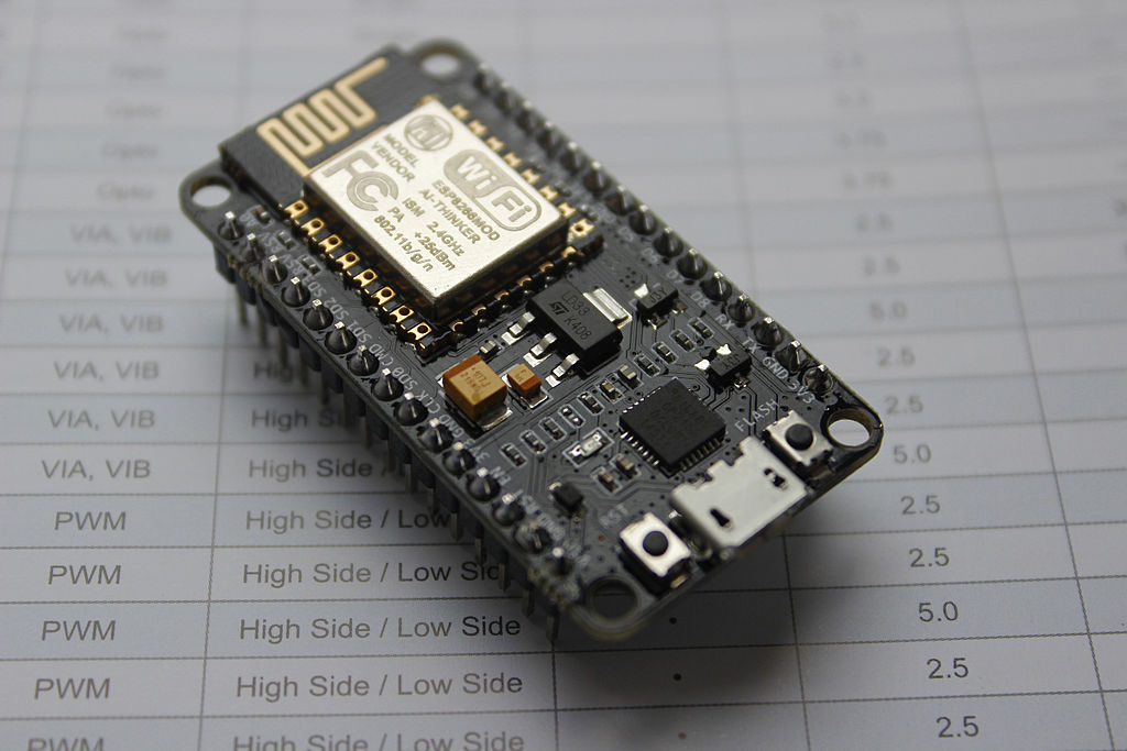 The other thing that I have done over the last year is to standardise on using the NodeMCU (hardware, not the LUA software). Especially when rolling out multiple small projects, it is immensely convenient to be able to plug a device into a USB port and just program it (automatically without having to wire up serial pins and then get the correct pins tied high / low for flashing / running). With no need to worry about providing 3.3V power, adding capacitors to prevent the ESP8266 power spikes from causing instability, or adding a resistor + cap for a power-on reset. No need to scale down the ADC input to 1V or to add my own test led… and all of this in a breadboard friendly package.
Also, just to be clear for those who may wish to follow along, I always use the “second generation” NodeMCU known as v2. The different versions are described here and I agree with that poster – i.e. don’t buy the v3 variant because its larger size means that it leaves no free breadboard holes on either side.
Unfortunately, with all this added convenience comes the drawback of added power consumption, which continues even when the ESP8266 is in deep sleep.
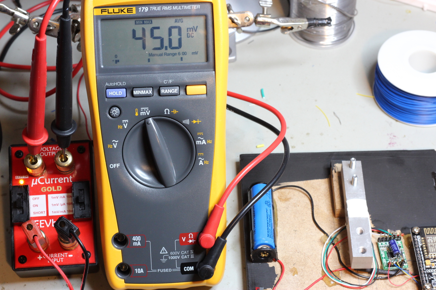
I measured 18mA to the NodeMCU board while the ESP8266 was in deep sleep mode – orders of magnitude more power hungry than I was looking for.
So for my iot-container project, I sought to retain the convenience of using the NodeMCU, but to address its power consumption shortcomings to allow battery operation.
Read further to hear what I did.
The two immediate suspects are the power regulator, and the UART, as discussed in the forum here.
The first step is to target the power regulator. The AMS1117 LDO draws a quiescent current of “typically” 5mA. To prevent this, it may be sufficient to lift just pin 1. However, I chose to remove the whole chip to free up space for later.
You won’t need the LDO if you supply your own power directly to the 3.3V pin of the NodeMCU. I often use a single cell Li-Ion battery via a 1N4001 dropper diode. Note that from now on you will need to supply this power, even if a USB cable is connected for programming / monitoring.
Place a small amount of flux and solder on the pins, starting with the big tag, and it should lift easily.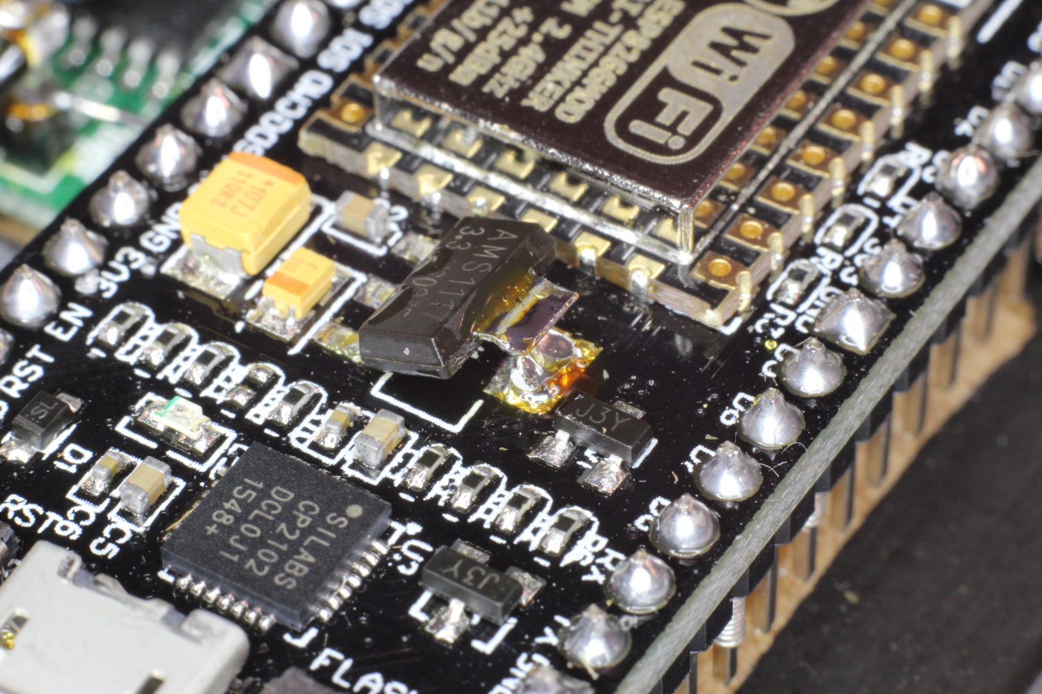 Then remove the remaining 3 pins. Without the LDO, I measured a saving of 3mA.
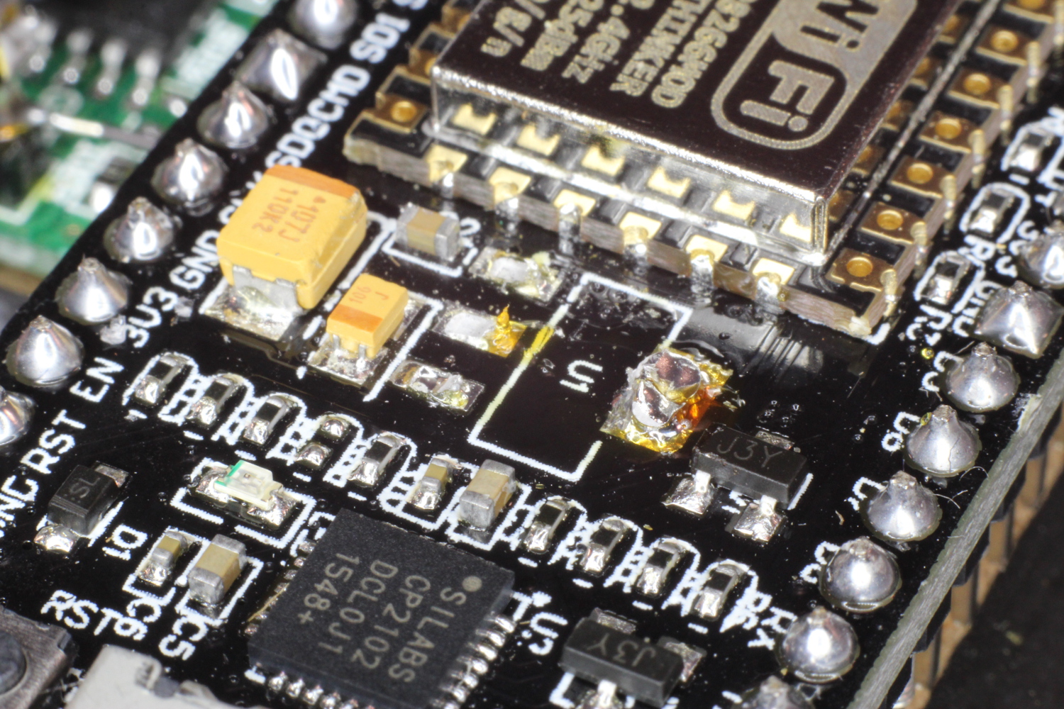
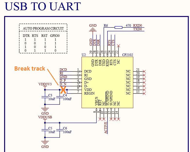
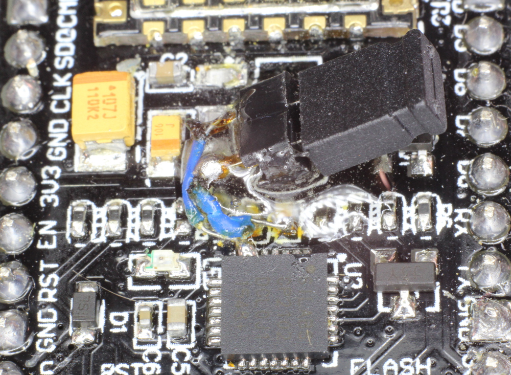
Now for the biggest saving – to disable the USB UART. This can be done with reference to the NodeMCU schematic by cutting power to pins 6 and 7.
In practice this means cutting a track with an X-Acto knife under the best magnification you can find, and with steady hands. Also scrape away the protective coating to the right side of the cut: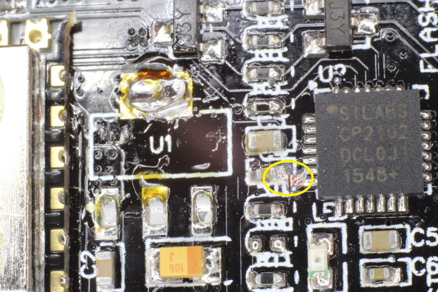
Congratulations! You will now have reduced power consumption by some 360x to around 50μA 20μA [Updated 28 Jan 2017 when I was powering only the NodeMCU, without additional circuitry].
Earlier I mentioned using OTA to program your device. If you have already installed the OTA code prior to cutting the track, in theory you could finish at this point, and permanently forego the use of the USB port. In real life, things go wrong, and it is useful to have the option of going back to having a serial port.
Option 1: Add Switch or Jumper
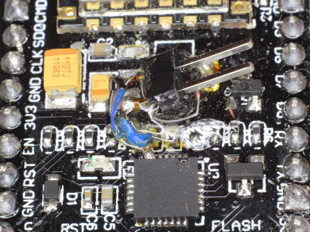
The first (and easier) option is to put a switch in the position formerly occupied by the regulator, attached to the two points shown below:
With this in place, you can re-enable the USB port for programming or debugging via the serial monitor.
A note to the unwary: The first time I tried this I glued down the switch with epoxy. The problem is that, unless you are more careful than I was, a drop of epoxy becomes suddenly HUGE under these magnifications. The glue seeped into the switch, preventing it from working, and the NodeMCU ended up in the bin. Second time around I used super glue with more success.
[Update 4 Sep 2016]: I have replaced the switch with a simpler and more reliable solution: a jumper.
Option 2: Power UART from USB (no switching required)
[Update 28 Jan 2017]: Thanks to Willem Jansen for suggesting this approach in the comments below. It turns out that the cp2102 UART has its own internal 5V to 3.3V regulator, which is not by default used by the NodeMCU circuitry, probably because it would not reliably supply the peak currents required by the ESP8266 (plus any associated circuitry the user might add around the NodeMCU).
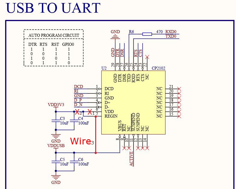 As explained in section 10 of the cp2102 datasheet, the cp2102 can be “configured as either a USB bus-powered device or a USB self-powered device”. To reconfigure the chip to use USB power requires isolating the VDD pin (break at X1) in addition to the X2 break described earlier, followed by permanently wiring the Regin pin to USB 5V (Wire3).
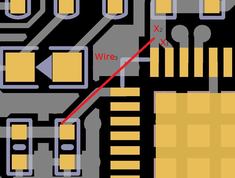 You can see on the right what this looks like. The extra PCB break really adds to the difficulty, even under 10X magnification.
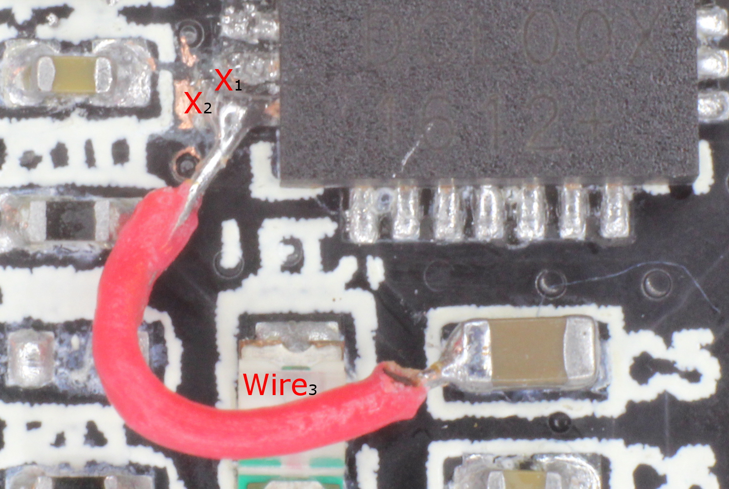 Once complete, the UART will only draw power when the USB is connected for programming / debugging. Certainly this is a more elegant solution and convenient to use – offset by the extra time and effort required to make the mod. Depending on how often you plan to update firmware or debug will determine which approach is optimal – you decide!
I need to warn you that after I implemented option 2, I found that intermittently the ESP8266 does not seem to boot up after applying power. Thanks to Mario Valentino – in the comments below – who found that a disconnected UART can pull the ESP8266 TX pin low, causing intermittent booting problems (as hinted at under “Desired level during power on” in: http://microchip.ua/esp8266/ESP8266_Module%20Application%20Design%20Guide.pdf). What I find strange is that in theory this should also be the case for option 1, yet I did not experience that.
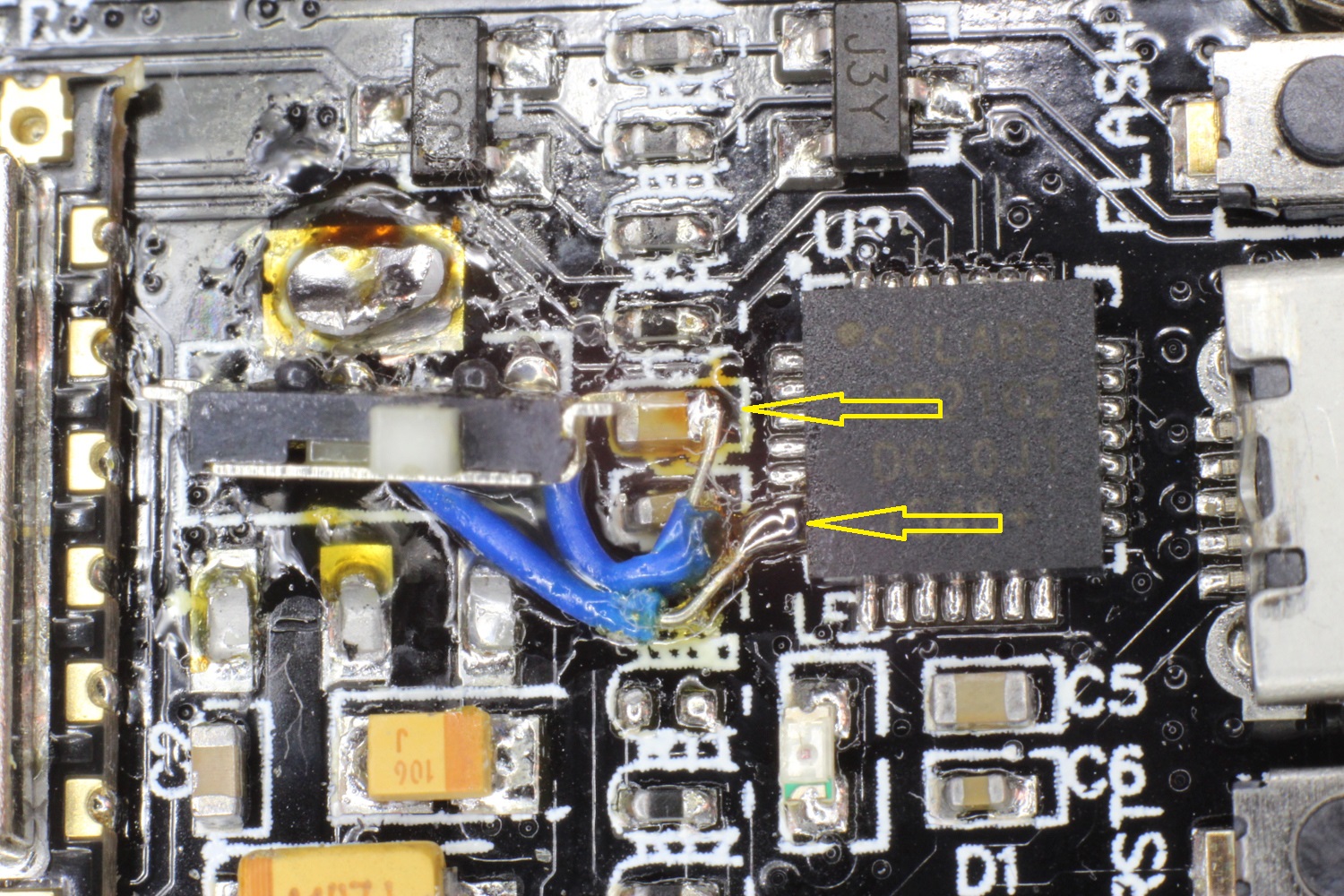
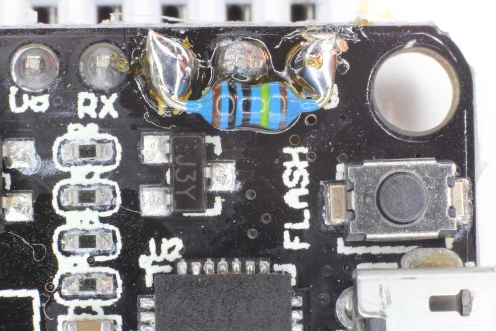 The solution is to place a resistor between TX and 3.3v, as shown on the right. Unfortunately this does waste some power. Choosing 1MΩ minimises this to an additional 3uA, bringing the total deep sleep current consumption of the NodeMCU to between 22-23μA.
Which option would I choose? I favour option 1. You save 5% power compared to option 2, and it is less tricky to make the mod. If you use OTA to update your firmware (or seldom update your firmware), you will not very often, if at all, need to replace the jumper to re-enable the serial port. Certainly, however, option 1 is not as “elegant”…
To be able to measure the small currents, I made use of the excellent μCurrent Gold.
You may correctly point out that 50μA is still several times higher than what should be achievable with just the ESP8266 alone. But for what I am doing it is good enough: (theoretically at least you could get towards 10 000 hours from a small 500mAh Li-Ion cell, depending of course on what you do during the wake up periods, and preferably only infrequently using Wi-Fi.
[Update 28 Jan 2017]: While testing option 2 above, I was powering only the NodeMCU (i.e. without the additional HX711 circuitry used previously). I measured deep sleep current at 20μA!
In my next post, I’ll put this into practice, with full code.
Interesting — it is a bit surprising that the CP2102 consumes so much power. The datasheet seems to indicate that it operates in a low power mode from reset until USB enumeration. Look for SUSPEND in the datasheet.
I’ll run some experiments as well.
Yes, I saw the SUSPEND lines mentioned in the datasheet, but they are outputs only. Suspend seems to triggered when “signaling is detected on the bus”. So I tried removing all “Serial” references in my Arduino code and also not plugging in a USB cable, but to no avail. Report back if you have any success!
Thanks for the great post! I’ve been tearing my hair out today trying to figure out why I could get that reported 70uA! Did you ever get a chance to follow up on the question of the CP2109 power consumption in suspend mode?
I just added a longish comment about suspend mode further down. Couldn’t get lower than 450µA though, as the CP2102 still draws 330µA in suspend mode according to the datasheet.
When the current gets really low, the diode will drop less voltage than you might expect and your module may get exposed to a voltage that is higher than its maximum spec. To avoid this problem, instead of a regular Li-Ion use a Lithium Iron Phosphate battery (LiFePO4), which has a nominal voltage of 3.2V and never goes higher than 3.6V. An easy way to experiment with them is to use the LiFePO4wered/USB module I sell on Tindie: https://www.tindie.com/products/xorbit/lifepo4weredusb/?pt=ac_prod_search
Hi, I’d like to use LiFePO4 batteries, but what is the minimum operating voltage of NodeMCU? What if battery voltage drops to 3v or less?
Thanks, I hadn’t heard of that type of battery – will check it out.
This is why i wish someone would come up with a proto and go version of nodemcu. Socket the actual nodemcu board for the ESP8266-12E and then sell a second board with just the socket wired to pins. Build and debug your prototype in the nodemcu and when complete pop the 12E out and into the socket only version.
I have seen several 3d printed sockets but think we are still a ways off. http://www.thingiverse.com/thing:1333056 for example but the pins used arent something standard off the shelf.
Or (epiphany here) maybe I wam thinking about it backward. Take a modern nodemcu board design, and move all parts other than the ESP8266 to a daughtercard that plugs into/onto the top of the nodemcu board. Doh they already have that http://www.aliexpress.com/item/ESP8266-serial-WIFI-Witty-cloud-Development-Board-ESP-12F-module-MINI-nodemcu/32569199462.html
Hmmm I wonder what one of these draws current wise without the serial board. Time to order one.
Haven’t stop to play with ESP8266 in the Low-power world, but I wonder how much time/energy it would used to connect to an Wifi network and send a simple message… keen to see the following post!
Not exactly an ESP8266, but this “Arduino” + RFM69 board consumes less than 4uA in sleeping mode and can be powered by standard AA batteries: https://talk2.wisen.com.au/product-talk2-whisper-node-avr/
I have ESP01 powered with 2000 mAh power bank and AMS1117. It lasts about 10-12 days waking up every 5 minutes for 10 seconds to connect to wifi, read DS18B20 and send data both to local MQTT and ThingSpeak.
Here is my test setup: https://pp.vk.me/c633522/v633522157/16852/Rt0LjMCpZ94.jpg
And here are readings: https://thingspeak.com/channels/64404
I was wondering if you could improve the running time by removing the LDO and also reduce time 10 seconds for just a few Milliseconds… I’m currently running an old version of the board I mentioned above for over 1.2 years on 2xAA. I know it’s not the same an it can’t send metrics directly to the Internet without a gateway but might be room for some improvement on the ESP8226. Other thing is the power bank, rechargeable batteries normally have a bigger self-discharge rate when compared with non-recharchable ones.
I’m not sure if ESP8266 can survive direct connect to LiPo battery as it’s voltage can be up to 4.2 V. In my case the longest step is WiFi connection, it takes about 5-6 seconds. Reading sensor and sending data adds 1-2 seconds. And I forgot to mention I’m using NodeMCU firmware running my Lua scripts. Probably clean C code could do the job much faster.
I’m pretty sure it is better to use simple broadcasting radio like 315/433 MHz or NRF24L01+ to save time on AP association, though I have not tried them yet.
i run all my esp8266’s at 4.2V
never even once had any issue. that would be 15 modules working simultaneously at 4.2V for 2 years straight.
never too hot, but as expected warmer than 3.5V for instance. no fan no heat sink needed for my usage, but do ensure good exposure to air at room temp.
Hello Mr. Tinkermax,
could you divulge which spefici battery you are partial to…?
Thank you in advance.
My proposal would be: Cut the UART power lines as indicated, scratch away the Vcc-pin and connect the REGIN pin (pin in the bottom left corner) to +5V from the USB directly. This way, the SILAB IC is only active when you attach a USB device – without necessitating any jumper at all.
Yes! I like your thinking. As per the cp2102 datasheet (section 10), the chip can be “configured as either a
USB bus-powered device or a USB self-powered device”. I will give your approach a try to confirm, and then update the post with this alternative.
If you power the CP2102 from a usb power supply, then it *ought* to go into suspend mode and consume much less current (at least, this is how I read the specs)
Great article. I want to reduce the power consumption of my ESP8266 NodeMCU as well and I am going to try Option 2: Power UART from USB (no switching required). I have one question though, do I need to still do the other adjustments as well, or does this suffice?
Kevin, for option 2 you still have to first make the mods described before the “option 1” heading. Just be aware that “option 1” is definitely robust and proven – and has been running my IoT device (/?p=1525) for almost 6 months on a single charge of a 14500 cell. However, I only tried option 2 last week and experienced some strange intermittent issues with the NodeMCU not booting – so cannot be as confident of its reliability.
I observed the instability with option 2 as well, especially when using deep sleep. About 1 in 3 times the module does not reboot after deep sleep when the CP2102 is unpowered.
Solution: Pull up the TX pin to 3.3v with a 10K resistor (higher may work as well). By disabling the CP2102 the internal pull up is gone as well and the ESP becomes unstable on boot.
Thanks Mario – I believe you mave have solved this! I must say I did consider something similar, but was thinking of the RX pin (since I thought it more likely to be an input). I couldn’t find any evidence that the TX pin (GPIO1) mattered at boot time. But doing another search there is something – look under “Desired level
during power on” for the TX pin at: http://microchip.ua/esp8266/ESP8266_Module%20Application%20Design%20Guide.pdf
I’ll confirm and update the post.
First of all, thank you Tinkermax for a brilliant tutorial.
I have followed Option 1 except I did not remove the voltage regulator, so I can still use a 5V powerbank. Unfortunately, my NodeMCU v2 does not boot without the jumper connecting the track I’ve cut. The blue LED does not even blink and the device draws about 35mA forever. If I wait for the LED to blink before I remove the jumper, it boots normally and when it falls to deepsleep, the current is 2.3mA (rather than 10mA when UART chip is connected).
I also tried to solder a 120kOhm resistor between TX and 3.3V but nothing has changed.
Does anybody have any idea what prevents my NodeMCU from booting? Do you think removing the voltage regulator makes any difference? Thanks.
Update: I have also removed the voltage regulator, so now it’s the Option 1 unmodified, but nothing has changed. Still doesn’t boot with the UART chip disconnected.
One possibility: are you putting the NodeMCU into deep sleep in your test software? If so, I found that I had to short 3.3v to ground briefly (with the power off / disconnected!) to cycle the NodeMCU. This is because the current draw is now so low that the onboard caps hold the ESP8266 powered in deep sleep mode for some time… so it can appear not to boot when you reapply power.
Thank you for your tip. I do put the NodeMCU into deep sleep. But it’s the same no matter if I put it into deep sleep or if I just disconnect the power supply. I tried to short 3.3V to GND before connecting the power supply briefly but it’s still the same. I also tried to measure resistance between 3.3V and GND with the NodeMCU off, and found quite surprising that the resistance was only around 1kOhm with the UART chip connected (jumper present), and around 2.5kOhm with the UART chip disconnected (jumper removed). Is this normal? Thanks. Unfortunately, I don’t have another v2 for reference.
I am going to try if I can use a PNP transistor to connect the UART chip only when the NodeMCU is running, and to disconnect it to save power when it goes to sleep.
My results with the CP2102 power trace cut at X2:
Needed 10k between tx and 3.3v for reliable booting/wake from deep sleep , otherwise it shows ~30ma always.
Tx pin voltage is 1.5 volts while sleeping , 2.44v while running . There
100K ohm would not boot
1) 2.3ma in deep sleep with CP2102 unpowered and AMS 1117 regulator still populated.
2) ~ 0.200ma in deep sleep with CP2102 unpowered and AMS 1117 regulator removed from board (I supply 3.3v to 3.3v pin_
…and experimenting with 10k,100k and no pullup resistors between 3.3v & Tx:
….10k works 0.200ma
…..100k doesn’t boot/wake 0.043ma
……no pullup (infinite res) doesn’t boot/wake 0.020ma
I had the same problem! after trying option 1, the chip would randomly either work or not work, and I was going crazy! I thought I’ve cut too much tracks or so that it’s now lost. But I kept trying to fix it since it did work sometimes but wasn’t sure what was stopping it from running normally!
I have tried to short 3.3V and Gnd pins, but still doesn’t always work:
So as ROBERTO ARANO mentioned, I tried connecting a resistor between 3.3V and Tx pins:
1) 50K ohm, doesn’t work
2) 10K ohm, doesn’t work
3) 1K ohm, works! Deep sleep current = 4mA
I suspect this would make it draw more current since it is a lower resistor value.
Next I will try to disconnect the Voltage regulator hopefully this would help me save more power and have longer battery life.
Any idea why a higher resistor value doesn’t make it work?
Just removed the Voltage regulator, It’s now down to 1.9mA in deep sleep. I was hoping I could go to less than 1mA. I guess 1.9 mA is as far as it gets for me. Might be because of the 1 Kohm between 3.3v & Tx pins, but it doesn’t work otherwise…
Dear all,
I want to provide supply to NodeMCU ESP8266 (v0.9) from powerbank (5000mah,10000mah and 20000mah and each has 2 ports). How could i achieve this ?
Purpose is to build robotic car so that using mentioned power bank ( one port goes to controller via to motors(Wheels) and other would be connected to ESP8266 ).
I require support and assistance .
Great hack ! If your wakeup period is periodic (always the time) you can use the TPL5111 Nano-Power System Timer for Power Gating ( http://www.ti.com/lit/ds/symlink/tpl5111.pdf ) you can configure the “deep sleep” period 100 ms to 7200 s and the IC draw only 35 nA… 😉 Just only mofset and resistor
Thanks for the tip on using TPL5111 . Note there is no data retention, even RTC memory, (e.g. for counting restarts) when you remove power from an ESP8266, Before reading your note I tried using a slow charging capacitor to toggle shutdown pin on an MCP1826 but the shutdown pin has a non-linear input
Nice tutorial got my esp8266 node mcu running without the 1 M ohm resistor and it’s consuming a 13 micro amps in deep sleep SWEET!
also i use a arduino uno without chip to program the sketch through rx and tx , so that could also be a solution number 4 for operation without uart.
now i have a microcontroller that can have a semi always on state running on the power from bacteria in a plant based microbial fuel cell
I’m guessing you also removed the silabs chip as well?
Feels like removing the chip and regulator and then programming through RX/TX pins with a USB UART -> TTL adapter would be easier and more reliable than cutting traces to me. If you don’t have one you can make one by using a separate NODE MCU, short EN to ground, then connect the RX –> RX and TX –> TX
My adafruit Huzzah goes into a proper deep sleep power consumption level without requiring these hardware modifications. Would love it it someone knew of a similar board that is in the price range of the Amica style boards.
I did some experiments with what options there are without cutting the board
TL;DR!
I got down to 450µA (with the regulator removed but leaving the board as it is), by using a custom made USB cable.
For my use-case I wanted to run the NodeMCU from a battery-pack. Therefore I have a somewhat limited current but I’m not speaking coin-cell-limited.
(I probably leave the regulator in, but i measured currents without it for comparison)
My 1st attempt (UNSUCCESSFUL) was writing the EEPROM of the CP2102 to change the value of “BUS POWERED” from NO to YES.
Changing it worked well, but didn’t change the power consumption.
Not sure if this can maybe be used to reduce the amount of cutting in option 2, or whether this is just a descriptor thing. But as I didn’t want to do any cutting, i gave up on this.
(I used http://cp210x-program.sourceforge.net to change the value)
My 2nd attempt (SUCCESSFUL) was sending the CP2102 in suspend mode.
(according to the datasheet, this reduces the CP2102 current from 26mA to 330µA)
The 2 “SUSPEND” pins of the CP2102 sounded interesting at first, but those are status outputs only.
** Suspending using a Linux PC **
First I was able to successfully send the CP2102 into suspend-mode from a Linux-PC
# find out which USB-Port the CP2102 is connected to (here: “3-1”)
echo -n “auto” > “/sys/bus/usb/devices/3-1/power/level”
echo -n “0” > “/sys/bus/usb/devices/3-1/power/autosuspend”
which automatically sends the CP2102 to suspend-mode if /dev/ttyUSB0 is not used
** Suspend using a USB-cable (NodeMCU with regulator) **
After reading up a bit about USB, I learnt that suspend means that the bus is idle for 3ms. (http://www.beyondlogic.org/usbnutshell/usb2.shtml)
But the DS2102 probably doesn’t detect that because there is no hub connected.
The hub is supposed to pull-down “D+” and “D-” with 15k resistors (while the NodeMCU is pulling-up “D+” with 1.5k)
So I built a USB-cable with:
* “D+” & “D-” cut-off from the power supply (as the power-supply has it’s own resistors, that were messing with mine)
* “D-” having a 47k resistor to GND (I didn’t have a 15k)
* “D+” i put a 470k resistor to GND (should be 15k but it would “fight” against the pull-up of the CP2102 causing power consumption, I don’t know whether this is even necessary, but the CP2102 may check levels before activating its pull-up, I don’t know)
This reduced the power consumption of my vanilla NodeMCU (with regulator) from ~18mA to ~3.6mA
Seldomly I noticed, that the DS2102 was not going to suspend right after connecting the USB-cable.
I’m not sure why, but to make sure that the suspend-mode is enforce I could pull-down “D+” to GND briefly after power up.
(both “D+” and “D-” in low-state for 10ms means “USB-RESET”, and “D-” is already low. This can probably be done from a GPIO, after that the GPIO-pin can be changed back to input/no-pullup, didn’t test that though)
** Suspend using cable without regulator **
When removing the regulator and powering the 3.3V directly, the DS2102 still needs to be powered from the USB connector to go into suspend.
It seems that 3.3V is enough for it to detect suspend, so I could feed the 3.3V from the NodeMCU into the 5V of the USB connector
(I put a diode in, so I don’t accidentally put 5V from a PC into the 3.3V of the NodeMCU)
Plugging in and out the USB connector a few times, makes the DS2102 exiting suspend. It can be re-entered by briefly pulling low “D+”, as mentioned above.
This reduced the power consumption of my NodeMCU without voltage regulator from 13.5mA to 420µA
Teschii: Good work!
Yikes! We good info and great sleuthing of datasheets! I have an Adafruit Huzzah32 (esp32) and it has the same issue: consumes 6.5mA in deep-sleep due to the cp2102.
As mentioned in my previous comment I had the same issue on an Adafruit Huzzah32. Unfortunately the trace that connects VDD to REGIN on its SIL CP2104 chip runs under the corner of the chip, so there is absolutely no way to cut that trace (without removing and replacing the CP2104). I did some experiments with the USB D+/D- lines and what I found is that grounding D+ _increases_ power consumption, but grounding D- _decreases_ it. I ended up wiring a 47K SMD resistor between ground and D-. The result is a deep-sleep power consumption that dropped from 6.5mA previously to ~250uA. It’s not where a good esp32 board should be, but it’s 25x better than before! The pull-down does not appear to interfere with USB operation (I haven’t tried a very long cable, though). Thanks again for your info, I would have never figured this out without it!
Thanks for this great article. I ran into the same problem with the NodeMCU v3.
It uses the CH340 USB-to-serial controller and in my case it was very easy to reconnect its ground pin to a cable to allow switching it on and off: https://itooktheredpill.irgendwo.org/2017/reducing-nodemcu-power-consumption/
Rumpeltux: Thanks for posting that – good to know that something similar is possible with the NodeMCU v3.
Could you please tell how exactly you connect 3.7V (4.2V max) Li Ion Battery into 3.3V input. Doesn’t it brick ESP8266? Diagram would be nice.
Anti: If you have a look at my other posts (e.g. IoT Container or Train ) you will find circuit diagrams. I use a diode (e.g. 1N4001) to drop the voltage by nominally 0.6V, which reduces the fully charged 4.2V Li-ion to 3.6V – which is within the tolerance of the ESP8266. It is not a “perfect” solution (e.g.compared to using an LDO like the CAT6219) but is very simple and efficient.
I have a analog-ish kludge that I found useful for low-power drain. I used a solar powered USB battery pack (available anywhere) to power a Nodemcu. The battery pack only outputs 5 v when there is sufficient load (~50 ma), or for 20 seconds after a switch on the pack is depressed. I jumpered across the switch with a PNP transistor that is driven by a cmos 555 timer powered directly from the li-ion battery. The timer fires, the pack turns on for 20 seconds – the Nodemcu starts, sends my data and goes to sleep (8-10 sec). With minimal deep sleep load, the battery pack turns off till the next timer cycle (5 minutes). The 4 extra wires (battery and switch) are a pain, but the 555 load is only 75 ua and I think it will run forever, as long as the sun shines.
Hello, you can use TPL5110 use only 35nA you can specify the time to start/stop only with a resistor from 100ms to 7200s.
The post below use TPL5110 with ESP8266 it is a french but you can use Google Translate
http://faire-ca-soi-meme.fr/electronique/2017/02/20/veilleuse-sur-pile-a-base-de-esp8266-arduino-led-rgb/
Kiki67100: I came across that solution and actually bought some TPL5110s last year, but haven’t got around to experimenting. I thinks that it offers a lower power alternative, but with some drawbacks:
1. The SMD packaging is not exactly friendly to use, unless you make your own boards (or use breakouts?)
2. I make use of the ESP8266 RTC memory, which retains key variables during deep sleep mode to activate Wi-Fi only when something has changed. Using the TPL5110 would require saving to flash – with potential number of write cycle limitations.
Ron, I like the simplicity of your solution – when there is solar energy available (unlike inside my fridge). Thanks for sharing!
I have exactly the same behaviour as ROBERTO ARANO. With CP2102 disabled I need 10k max on TX to wake reliably from deep sleep. This adds an extra 190uA 🙁
I’m looking for absolute minimum power consumption to do some tests running on supercaps. I have replaced the AMS1117 with the HT7333 being able to power via usb-connector and use option 1 to switch off the CP2102.
Is there anything else I can try?
Ultimately I remove the CP2102 all together and do updates via OTA only, but of course it would be nice if I could still use the CP2102 sometimes …
The nodemcu is mainly a nice formfactor for the ESP-12E on a breadboard 🙂
I’ve implemented the low power solution, option 2. Works well, but 1M didn’t work for me, and I didn’t like the 10k option, as:
a) Takes too much current
b) would be partially powering up the ‘off’ CP2102 via it’s substrate diodes on the RXD input – yuck ! Could damage it eventually.
Instead I’ve come up with an Option 3 that appears to work quite well.
1) Cut the track to TXD0 between the ESP module and the CP2102, but on the ESP side of the via that goes to “TX” pin on the header.
2) Run a schottky diode such as 1N3132 from TXD0 pin on ESP module (pin 22 is the last pin) to the TX header pin (which still connects to the CP2101).
3) A 1k pullup from TX ideally would go to VDD (pin 6 on CP2102). My soldering gear isn’t up to getting a wire onto VDD as well as onto REGIN, so instead I took the pullup to Vin on header (about 4.8V after the sk diode from Vbus), and ran a ~3.5V zener to ground so the voltage on TXD0 doesn’t exceed 3.3V or so. You could use two 1N4001s in series from Vin to the 1k instead, if you don’t have a convenient zener lying about.
The fairly aggressive 1k pullup is need to ensure the port still works at 115k, but we don’t really care about the current here as it’s from Vbus.
Now the TXD0 pin on the ESP module can happily be pulled high by the weak internal pullup when sleeping, till it becomes a real TX pin output when running.
Resets/chip_en are now reliable.
I’ve since found, using a slightly different PCB cut, that the 1k pullup can easily go to the regulated 3v3 from the CP2102. The two bypass caps are included on the 3v3 regulated output too, which is much better.
You need to isolate *just* the REGIN pin with the cut, but VDD remains connected to the bypass caps.
To the side of the larger bypass cap, you also need to cut the track that connects this VDD to the 3v3 on the NodeMCU. Add a new bypass cap on NodeMCU 3v3 on the pads of the removed regulator (to mkae up for the ones just removed from the 3v3 circuit above).
PS: If you don’t have a schottky diode on hand, a small signal germanium detector diode (crystal set diode) works fine also.
Oops, I should mention the schottky points towards the ESP TXD0 pin 22, so a low on the module results in an (almost) low on the CP2101, but when it goes high, we are relying on the pullup.
lol this is a dev board, let it be a dev board, why not get a more barebone board? Such as RobotDyn’s ESP8266-PRO, it still have the same LDO but no need to worry about the serial chip..but the EEPROM is only 8Mb…
I think a lot of complication, the Wemos D1 Mini is much more efficient. Without any modification consumes 0.15mAh in sleep
Yeah but the Wemos doesn’t have that many GPIOs broken out, I was looking for drop-in replacement for the AMS1117 in SOT223 with the same pin out and came across AP2114, not as cheap but relatively affordable, has 200mV dropout at 500mA, 1A output max and 60uA quiescent current, not bad at all.
The MCP1700 and HT7333 have much lower quiescent current but can only handle 250mA, pinout differs (Vin/Vout switched) which is like the bare minimum for the ESP alone, may work ok with adequate caps..
The Wemos uses a ME6211, 500mA, dropout 260mV at 200mA load (700mV at 500mA), quiescent current 60uA also but not available in the same package (SOT23, SOT89) and different pinout again.
It’s almost as if the specifically designed the pinout of the AMS1117 to be NOT compatible with others LDO so that once you design your board around it, you’re kinda stuck with it lol
AP2114H* (HA have a different pinout)
wow mate, you have some seriously killer SMD soldering there… if I tried to solder a nodeMCU board it’d be DOA in no time lol
Great article, well done!
I noticed that in the NodeMCU ESP-32S, they use approach #2, the CP2102 is only powered when USB is connected.
It can be seen here:
http://esp32.net/images/Ai-Thinker/NodeMCU-32S/Ai-Thinker_NodeMCU-32S_DiagramSchematic.png
I do not see a resistor in there to pull up the TX line. I suspect the reason it happened to you is because you also cut the traces to the capacitors on the VDD pin, perhaps they are needed. Maybe its better to cut the trace from VDD3V3 to these capacitors, and instead, add capacitors for stabilizing 3V3 on your 3V3 source\board.
Thanks for this topic and all comments.
(My program : send HTTP request when RST then go deepsleep.. if wifi can’t connect until 5 sec : go deepsleep.)
Everything was working OK on USB & Battery before the mod.
After some tries : For me option 1 & 2 didnt work.
Option 2 with 22k pullup resistor between 3.3v & tx works sometimes…. not always.
When it doesnt work, nodemcu ask like 350mA for eternity.
I tried to just remove CP2102 but nothing work without this chip.
Then… I loosed this tiny cp2102 chip =D
I resoldered an other cp2102 chip that I found in my old chips box (not a new chip.. could be not working good) but …. now it’s still not working all the times in battery mode (3.3v powered) but works good powered by USB… maybe something is wrong with this cp2102… anyway.
I’m bored, I’ll buy a “D1 mini” and avoid nodemcu for battery projects.
when I resoldered the other cp2102, I didnt mention that I set it back to original : solder back the asm1117, removed the 22k pullup R, rewire cp2102 pinout 6&7 to capacitor.
Hi, I tried to do the same on an ESP32 board, but got a “Brownout detector was triggered” error in the serial console. I thought it’s because my MCP1700-3.3v voltage regulator is not powerful enough, so I cranked up my decoupling capacitor to 2.2mF (and later even 1F supercap). The error remains the same.
Hi,
I want to add some important points to this mod.
I tried Option 2 = USB bus powered + Removed regulator.
First thing, nothing more than a 10K resistor works for me between TX and 3V3.
After putting the 10K resistor, the power consumption goes down to about 0.2mA in deep sleep. Much better than the previous 9.5mA with the CP2102 intact.
But, I noticed something very strange. Although the sleep power consumption was as expected, the power consumption during normal operation was decreasing and increasing by 10mA when I was plugging and unplugging the USB respectively. That means, during normal operation when powering the board from an external 3V3 source, it consumed about 70mA when the USB was also plugged into a PC; but that increased to 80-85mA as soon as I unplugged the USB while the external 3V3 was still present. I also found around 2.5V at the USB cable VBUS, even when it was only connected to the nodemcu at one end and the other end was detached from PC.
After a lot of head scratching, I found out that since in normal operation, if you use serial.begin in your sketch, the TX and RX pin is pulled high by the MCU. This causes reverse current to flow into the RX and TX pin of the CP2102, and waste around 10mA. And, as expected, as soon as the USB was plugged in, this wastage was gone because now the CP2102 has its own power source. This behaviour might be harmful for the CP2102 in the long run.
SOLUTION :
In void setup(), you’ll have to change the pinmode of the TX and RX pin of the esp to normal GPIO and make them input, with a digitalWrite LOW on them. This way, as soon as the ESP powers on, it will turn off the TX and RX pin and no reverse current will flow into the CP2102. And you will lose the ability to communicate via UART, but you’ll gain two digital inputs, and save 10-15mA of power. [note, TX pin will only be active low because of the 10k pullup].
How to switch Tx and Rx to GPIO :
put the following code in void setup() :
//********** CHANGE PIN FUNCTION TO GPIO **********
//GPIO 1 (TX) swap the pin to a GPIO.
pinMode(1, FUNCTION_3);
pinMode (1, INPUT);
//GPIO 3 (RX) swap the pin to a GPIO.
pinMode(3, FUNCTION_3);
pinMode(3, INPUT);
//**************************************************
digitalWrite (1, LOW);
digitalWrite (3, LOW);
Thanks for the great post. I am also trying to set up a bit of IoT at home but stucked at one issue and cannot move forward. Since you are experianced in NodeMCU you may know the solution.
Every time I try machine.deepsleep(msecs) ESP is being waken up for a random number of times but never continue working till battery is drained.
From the log I am writing to the last command is deepsleep itself. I tried attach my ESP to 2 different powerbanks and a power supply but the result is the same.
Strange thing is when I attach ESP to RPi3 USB port I am able to rshell even though it supposed to be asleep (stopped sending mqtt messages).
Still fighting with this issue but I am really tired of it. The code is in micropython it this is relevant.