[Update May 2016: for reducing power consumption of a NodeMCU board, see this post where I revisit the topic].
In my previous post, I mentioned that one of the reasons that I was excited about MQTT was because of its potential to allow power savings schemes on the ESP8266. The MQTT broker could asynchronously hold messages during the period that the ESP8266 was in a sleep cycle, to ensure that nothing is missed while dramatically reducing average power consumption.
This week I have hit a few obstacles, mainly due to the immaturity of current implementations of some of the latest MQTT qos (quality of service) features – at least that is what I suspect at this point. But more on that next week.
So, focusing on the ESP8266: my initial research had led me to believe that “deep sleep” mode was the way to go. Who can argue with using just 78μA during deep sleep?
To be able to implement deep sleep (without adding extra hardware to generate a wake-up signal), you need to link 2 pins on the ESP8266, as discussed here. Fortunately, the ESP-03 module has pads broken out on the PCB that you can join together. By linking these, you lose the ability to use GPIO16, but gain an automatic wake-up from deep sleep after the number of microseconds that you specify in the system_deep_sleep(time_in_us) call. You can understand better how this works by looking at the ESP-03 schematic.
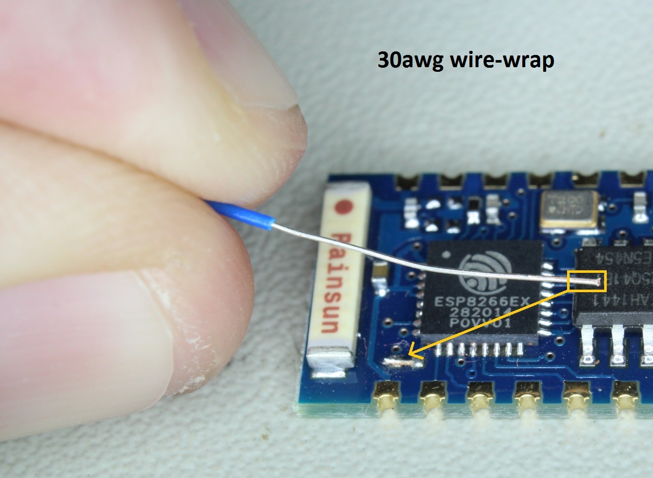
To avoid any confusion, the pads to join are shown below:


The easiest method to achieve this would be to use a zero ohm SMD resistor. I didn’t have any, so I used a short section of 30awg wire-wrap wire which I first tinned and then snipped to the correct length. I had a moment of difficulty getting the piece of wire to unstick from the soldering iron tip. An approach that worked better on my second device was to solder one end of the small wire link first. Surface tension then helps hold the link down onto the board while you finish.
To test it out, I put this command at the end of the mqttDataCb routine so that deep sleep would be initiated when I sent an MQTT message to the ESP8266:
system_deep_sleep(30000000);
Sure enough, the device went to sleep, and woke up after 30 seconds!
What I hadn’t fully appreciated was that the device does a FULL RESET, starting up again and re-running user_init(). This means that the ESP8266 has to re-establish connectivity, both to the Wi-FI and the MQTT broker, which can take much longer than I would like. Two of the steps that seemed to take time (sporadically), were talking to the DHCP server, and the DNS resolution of the MQTT broker.
Firstly, to eliminate the DHCP step, I found this useful code, which allows you to specify a static ip for the ESP8266 (note that I have hardcoded my information). The code goes into the WIFI_Connect routine found in wifi.c.
struct ip_info info;

info.ip.addr = ipaddr_addr("192.168.1.18");

info.netmask.addr = ipaddr_addr("255.255.255.0");
info.gw.addr = ipaddr_addr("192.168.1.254");

wifi_set_ip_info(STATION_IF, &info);
Secondly, to eliminate the DNS step, I configured the ip address of the MQTT broker, instead of its name.
With this streamlining in place, and when everything connects smoothly, waking up still takes 5 – 6 seconds. This would be perfectly acceptable in a typical scenario where the ESP8266 is acting as a sensor, sending readings periodically. Even sending a reading once per minute, the device could be in deep sleep for 90% of the time. Sending only once every 5 minutes translates into deep sleep for 98% of the time, and so on… you get the idea.
But in my wristband project, where the ESP8266 is waiting to receive an alert preferably with a latency of under 10 seconds, this deep sleep approach is (sadly) unworkable.
What about the other sleep modes? The information about these is rather scattered and scarce. The best I could find was this and this.
For these sleep modes, you do not specifically issue a sleep command. Rather, you specify a sleep type using wifi_set_sleep_type(sleep_type), which the ESP8266 then implements in the background.
Sleep type can be one of three values:
NONE_SLEEP_T
LIGHT_SLEEP_T
MODEM_SLEEP_T
MODEM_SLEEP_T is the default, NONE_SLEEP_T means even less power saving, so LIGHT_SLEEP_T sounds hopeful in that it reduces CPU power in addition to Wi-FI power.
But how do you actually compare power consumption? Using a meter is no good, as the current drawn is fluctuating all the time.
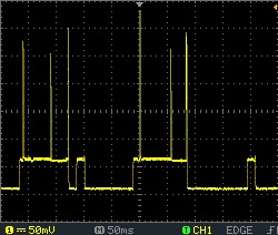
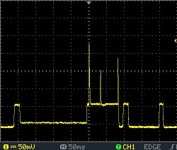
 To get an idea of what was going on, I connected an oscilloscope across a 1 ohm resistor placed in series with the power supply to my esp8266 breadboard. With default power savings settings, these images show the activity I observed while the ESP8266 was functioning as an MQTT client. I don’t know precisely the value of my 1 ohm resistor, so can only approximate the current consumption. But to provide some scale, the base is about 13mA, the steps are 70mA, and the brief spikes go above 300mA.
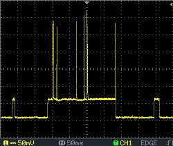
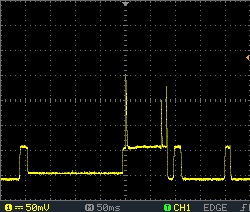 Next, I tested the light sleep mode by calling wifi_set_sleep_type (LIGHT_SLEEP_T ) at the end of the user_init() routine. The consumption was markedly reduced. Now the overall base was effectively zero (below what I could measure using this simple method), the next base up was at 10mA, the steps 60mA and the spikes to over 250mA.
I really need something that integrates over time to gauge the overall power consumption!
So, all in all, some interesting findings, although more relevant to other ESP8266 projects and not so much to my wristband.
Are there any drawbacks to using LIGHT_SLEEP_T? Other than obviously with a lower CPU power it’s taking longer to complete actions, consuming in some cases more power?
My experience was that it may make the wifi connection less stable (i.e more likely to drop out and have to reconnect), especially under poor signal conditions. But I really have not used this mode enough to be certain. I’ll get back to it at some stage and try to find out something more definitive. Let me know what you find!
Hey a suggestion for how to solder the bridge wire onto the pads: hold the wire as shown in your last picture, solder the end of the wire across the pads, and then use fine diagonal cutters to cut the excess wire off. That would completely solve the “sticking to the soldering iron” problem you mention.
Great idea… wish I’d thought of that!